
Understanding the Output Voltage of Arduino Architectures
When interfacing microcontrollers with external sensors, actuators, or communication buses, understanding and correctly configuring the output voltage of Arduino boards is critical. A mismatch in logic levels can lead to degraded signal integrity, erratic behavior, or catastrophic failure of sensitive 3.3V components when driven by 5V pins. This configuration guide breaks down how to manage digital logic levels, simulate analog voltages via Pulse Width Modulation (PWM), and configure true Digital-to-Analog Converters (DAC) across the Arduino ecosystem.
Digital Logic Levels: 5V vs 3.3V Board Comparison
The baseline HIGH output voltage of an Arduino digital pin is dictated by its operating voltage (VCC). While legacy boards operate at 5V, modern ARM-based and IoT-focused boards have standardized around 3.3V to improve power efficiency and align with modern sensor standards.
| Board Model | Microcontroller | Logic HIGH Voltage | Max Current Per Pin | Best Use Case |
|---|---|---|---|---|
| Arduino Uno R3 / R4 Minima | ATmega328P / RA4M1 | 5.0V | 20mA (Absolute Max 40mA) | Relays, 5V logic ICs, basic LEDs |
| Arduino Nano 33 IoT | SAMD21 (ARM Cortex-M0+) | 3.3V | 7mA | Modern I2C/SPI sensors, WiFi/BLE |
| Arduino Mega 2560 | ATmega2560 | 5.0V | 20mA | High pin-count 5V robotics |
| Arduino Giga R1 WiFi | STM32H747 | 3.3V | 25mA | High-speed DSP, audio, true DAC |
Configuring Pseudo-Analog Output via PWM
Most standard Arduino boards lack a true DAC. Instead, they simulate variable output voltages using PWM via the analogWrite() function. According to the official Arduino analogWrite reference, this function outputs a steady square wave with a default 8-bit resolution (0 to 255).
Hardware Timer Frequencies
The actual frequency of the PWM signal varies by pin and board. On the ATmega328P (Uno/Nano):
- Pins 5 and 6: ~980 Hz (Driven by Timer 0, which is also tied to
millis()anddelay()functions). - Pins 3, 9, 10, 11: ~490 Hz (Driven by Timers 1 and 2).
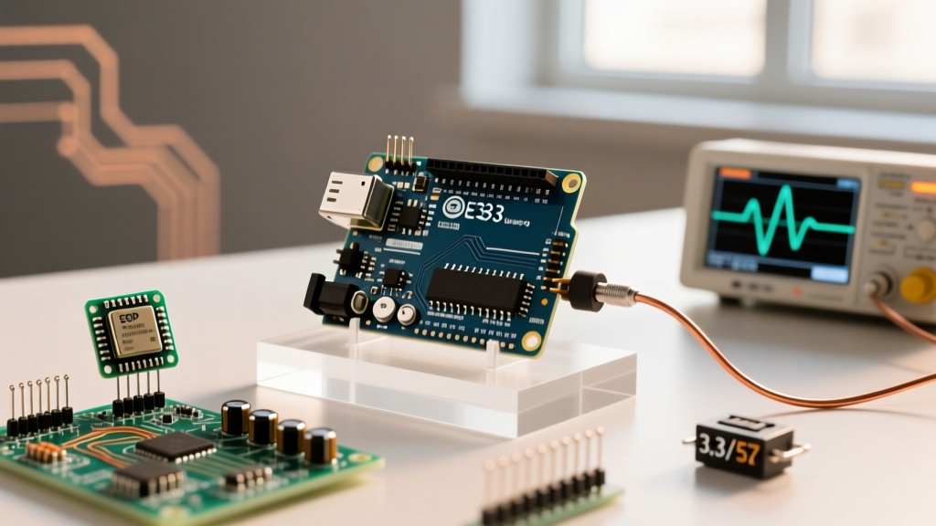
A duty cycle of 127 (approx 50%) on a 5V board yields an average voltage of 2.5V, but an oscilloscope will show the pin rapidly switching between 0V and 5V. This is fine for driving LEDs or DC motors, but unacceptable for analog audio or precision voltage references.
Step-by-Step: Building an RC Low-Pass Filter
To convert a PWM square wave into a smooth DC voltage, you must configure a passive RC (Resistor-Capacitor) low-pass filter. The cutoff frequency ($f_c$) must be significantly lower than the PWM frequency to effectively smooth the ripple.
- Select Components: Choose a 10kΩ resistor and a 100nF (0.1µF) ceramic capacitor.
- Calculate Cutoff Frequency: Using the formula $f_c = 1 / (2 \pi R C)$, the cutoff is approximately 159 Hz. This provides excellent attenuation of the 490Hz PWM carrier wave.
- Wiring: Connect the PWM pin to one lead of the 10kΩ resistor. Connect the other resistor lead to the positive lead of the capacitor and your analog load. Connect the capacitor's negative lead to GND.
- Buffer the Output: Because the 10kΩ resistor limits current to less than 0.5mA, you must buffer the filtered signal with an op-amp (like the LM358 or MCP6001) configured as a voltage follower before driving any meaningful load.
True Analog Output: DAC Configuration on Advanced Boards
For applications requiring genuine analog waveforms without the latency and ripple of PWM filters, you must use boards equipped with a hardware DAC, such as the Arduino Due, Zero, or Giga R1. Configuring the output voltage of Arduino boards with DACs requires adjusting the bit resolution.
Setting DAC Resolution
By default, analogWrite() operates at 8 bits even on DAC pins. To unlock 12-bit precision (0 to 4095), you must configure the resolution in your setup() block:
void setup() {
  // Configure DAC for 12-bit resolution
  analogWriteResolution(12);
}

void loop() {
  // Output exactly 1.65V on a 3.3V board (4095 / 2)
  analogWrite(DAC0, 2048);
}
For deeper technical parameters on modifying bit-depth across different ARM architectures, refer to the Arduino analogWriteResolution documentation.
The Arduino Due DAC Edge Case
Makers frequently encounter a specific failure mode when using the Arduino Due (SAM3X8E). Unlike modern boards that output 0V to 3.3V, the Due's DAC pins (DAC0 and DAC1) have a restricted hardware output range of 1/6 to 5/6 of VCC. On a 3.3V board, this means the true analog output voltage spans from 0.55V to 2.75V. Attempting to write 0 or 4095 will not yield 0V or 3.3V; it will clip at the hardware limits. If your circuit requires a true 0-3.3V swing, you must use an external DAC IC (like the MCP4725) via I2C.
Interfacing Mixed-Voltage Systems Safely
When your project requires mixing 5V actuators with 3.3V microcontrollers, configuring safe voltage translation is mandatory. The SparkFun guide on logic levels outlines several methodologies, but here are the two most reliable for maker configurations:
- BSS138 MOSFET Bidirectional Shifter (~$0.80): Ideal for I2C buses. Uses N-channel MOSFETs and pull-up resistors to safely translate 3.3V SDA/SCL lines to 5V without risking bus contention.
- TXB0108 / TXS0108E Auto-Direction Transceiver (~$1.50): Best for SPI, UART, and parallel data lines. Features built-in one-shot edge rate boosters for clean signal transitions, but cannot be used on I2C buses due to the open-drain nature of I2C.
Expert Tip: Never use simple resistor voltage dividers for high-speed digital signals (like SPI clocks above 1MHz). The parasitic capacitance of the PCB traces and the receiving pin will combine with the divider resistors to create an unintended low-pass filter, rounding off the square wave edges and causing data corruption.
Frequently Asked Questions
Can I power a 5V relay directly from an Arduino digital pin?
No. While an Arduino Uno outputs 5V on its digital pins, the ATmega328P can only safely source 20mA per pin. A standard 5V relay coil typically requires 70mA to 90mA. Drawing this current will overheat and destroy the microcontroller's internal silicon traces. Always use a logic-level MOSFET (like the IRLZ44N) or an optocoupler relay module to switch the high-current load.
Why does my multimeter read 2.5V when I use analogWrite(pin, 127)?
Standard digital multimeters measure the average DC voltage over time. Because analogWrite() generates a 490Hz square wave switching between 0V and 5V, a 50% duty cycle (value 127) results in an average reading of 2.5V. To see the actual 0V-5V square wave, you must use an oscilloscope or a logic analyzer.
How do I get a negative output voltage from an Arduino?
Arduino GPIO pins cannot output negative voltages relative to board GND; they are limited to 0V to VCC. To generate negative voltages (e.g., -5V or -12V for op-amps or audio gear), you must configure an external DC-DC inverting charge pump IC, such as the ICL7660 or MAX1044, powered by the Arduino's 5V pin.