
The Evolution of the Graphical User Interface Arduino Stack
The modern graphical user interface Arduino ecosystem has evolved far beyond the days of manually coding X/Y pixel coordinates and blocking delay loops. In 2026, professional makers and embedded engineers rely on hardware-accelerated rendering, visual design tools, and advanced memory management to build fluid, smartphone-like touchscreens on microcontrollers. When planning your next graphical user interface Arduino project, optimizing your workflow is no longer just about writing cleaner C++; it is about selecting the right display interface, configuring Direct Memory Access (DMA), and leveraging visual pipelines like LVGL v9 and SquareLine Studio.
Legacy libraries like Adafruit_GFX or MCUFRIEND_kbv are excellent for simple text readouts, but they fail under the weight of complex animations, anti-aliased fonts, and multi-layered widgets. To achieve a 30 FPS to 60 FPS render rate without starving your main application logic, you must fundamentally restructure how your MCU handles frame buffers, touch polling, and asset loading.
Hardware Selection Matrix for GUI Workloads
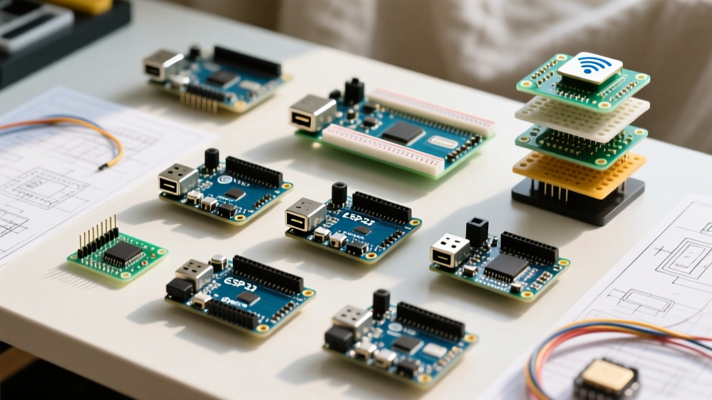
Before writing a single line of UI code, you must match your MCU's memory architecture to your display's resolution. A 480x480 pixel display using 16-bit color (RGB565) requires 460,800 bytes (approx. 450 KB) for a single full-frame buffer. Most standard Arduinos lack this SRAM. Here is how the top boards compare for GUI workloads:
| MCU Board | RAM / PSRAM | Display Interface | Est. Price (2026) | GUI Suitability |
|---|---|---|---|---|
| Arduino GIGA R1 WiFi | 512 KB SRAM / 16 MB Flash | Parallel RGB / SPI | $115.00 | Excellent (Supports parallel RGB565 displays natively) |
| Arduino Portenta H7 + Vision Shield | 1 MB SRAM / 8 MB SDRAM | MIPI DSI / SPI | $145.00 (w/ shield) | Professional (External SDRAM allows full-frame double buffering) |
| ESP32-S3 DevKit (Arduino Core) | 512 KB SRAM / 8 MB PSRAM | RGB Parallel / QSPI / SPI | $12.00 - $18.00 | High Value (PSRAM enables massive image asset caching) |
Note: While the ESP32-S3 is technically an Espressif product, the official Arduino core support makes it a staple in the graphical user interface Arduino workflow for cost-sensitive, high-performance deployments.
Memory Allocation and Buffer Math
The most common point of failure in MCU GUI development is the Out-Of-Memory (OOM) crash caused by naive buffer allocation. Let us break down the exact mathematics of a standard 4.0-inch 480x480 IPS display.
- Total Pixels: 230,400
- Color Depth (RGB565): 2 bytes per pixel
- Full Frame Buffer: 460,800 bytes (450 KB)
If you are using the Arduino GIGA R1 WiFi, which features 512 KB of SRAM, allocating a single full-screen buffer leaves only 62 KB for the MbedOS kernel, LVGL heap, and your application variables. Double buffering—a requirement for tear-free rendering—will instantly crash the board.
The Partial Buffer Solution
To optimize your workflow, you must configure partial buffers. By allocating two buffers sized to 1/10th of the screen (480x48 pixels = 45 KB each), you consume only 90 KB of SRAM. The LVGL official documentation details how the rendering engine automatically divides the screen into horizontal stripes, flushing each stripe to the display controller via SPI or Parallel bus while the CPU renders the next stripe in the background.
Step-by-Step Workflow: From Design to Deployment
Stop hardcoding UI elements in your IDE. The industry-standard workflow now separates design from logic.
Step 1: Visual Design and Asset Compression
Use SquareLine Studio to visually design your interface. Export the project as an Arduino/C++ LVGL project. Crucially, optimize your image assets before importing them. True-color PNGs with alpha channels will bloat your firmware binary and cause SPI bus congestion. Convert all UI icons to RGB565 color depth with a 1-bit alpha mask, or utilize LVGL v9's built-in LZ4 compression for binary image blobs stored in Flash memory.
Step 2: Configuring DMA and SPI Clock Phases
When using SPI displays (like the popular ST7796 or ILI9488 controllers), standard software SPI or unbuffered hardware SPI will bottleneck your CPU. You must enable DMA. On the Arduino GIGA or ESP32-S3, configure the SPI clock to 80 MHz. Ensure your SPI Mode is set correctly (typically Mode 0 or Mode 3 depending on the display IC). Misconfigured clock polarity (CPOL) and clock phase (CPHA) will result in a white screen or scrambled pixels, a common edge case that wastes hours of debugging.
Step 3: Decoupling Touch Polling from the Render Loop
Never place your touch controller read function inside a blocking loop. Most budget capacitive touch ICs (like the CST816S) communicate over I2C. Polling an I2C bus at 100 kHz takes approximately 2 milliseconds per read. If your LVGL task handler runs every 5 milliseconds, touch polling is consuming 40% of your UI thread's time. Optimize this by:
- Increasing the I2C bus speed to 400 kHz (Fast Mode).
- Utilizing the touch controller's hardware INT (interrupt) pin to trigger a flag, allowing the MCU to sleep or process other tasks until a physical touch occurs.
Common Failure Modes and Edge Cases
Even with an optimized pipeline, embedded GUIs present unique hardware-level challenges. Keep this troubleshooting matrix handy:
- Screen Tearing (VSYNC mismatch): Occurs when the display's internal refresh cycle overlaps with your MCU's buffer flush. Fix: Implement a hardware TE (Tearing Effect) pin interrupt. The display controller pulls the TE pin high during the vertical blanking interval; configure your DMA to only initiate the buffer flush when this interrupt fires.
- MbedOS Stack Overflows: LVGL widgets (especially complex charts or dropdown lists) allocate memory dynamically. On MbedOS-based Arduinos, the default thread stack size is often too small. Fix: Increase the main thread stack size in your
mbed_app.jsonconfiguration file to at least 16 KB. - SD Card Bus Contention: If your UI loads images from a MicroSD card, and the SD card shares the same SPI bus as your display, the UI will freeze during file reads. Fix: Use an SDIO-compatible SD card slot (available on the Portenta H7 and GIGA R1) to offload storage traffic to a separate hardware peripheral, leaving the SPI bus exclusively for the display.
Pro-Tip for 2026: If you are deploying a graphical user interface Arduino project in an industrial environment with high electromagnetic interference (EMI), avoid SPI displays. The high clock speeds required for SPI GUI rendering are highly susceptible to noise. Opt for parallel RGB interfaces or RS485-based HMI modules (like Nextion) where the rendering is offloaded entirely to the display's internal SoC.
Conclusion
Optimizing a graphical user interface Arduino workflow requires a holistic approach that bridges visual design software, precise memory mathematics, and hardware-level peripheral configuration. By leveraging partial DMA buffers, decoupling touch interrupts, and selecting the correct MCU architecture for your resolution, you can transform a laggy, pixelated prototype into a responsive, commercial-grade embedded interface.