
Why Migrate to a 12V Power Architecture?
When you first start building with microcontrollers, powering your board via a standard 5V USB cable is perfectly adequate. However, as projects evolve from simple LED blinkers to complex robotics, home automation nodes, or automotive telemetry systems, the 500mA limit of a standard USB port becomes a severe bottleneck. In 2026, with the widespread adoption of power-hungry peripherals like solid-state LiDAR modules, high-torque servos, and Wi-Fi/Bluetooth enabled boards like the Arduino Uno R4 WiFi, migrating to a dedicated Arduino power supply 12V architecture is no longer optional for advanced makers—it is a necessity.
This migration guide will walk you through the electrical engineering principles, thermal limitations, and practical wiring steps required to safely upgrade your project from USB or 9V battery power to a robust 12V DC infrastructure.
⚡ The Migration Threshold: If your project draws more than 300mA on the 5V rail, utilizes inductive loads (relays, solenoids, DC motors), or requires deployment in an environment without a USB host (like a weather station or vehicle), you must migrate to a dedicated 12V power supply with stepped-down regulation.
The Linear Regulator Bottleneck: Understanding Thermal Limits
To understand why simply plugging a 12V wall adapter into the Arduino's DC barrel jack isn't always the best solution, we must examine the onboard voltage regulation. Classic boards like the Uno R3 and Nano utilize a linear regulator (typically the NCP1117ST50T3G or AMS1117-5.0) to drop the input voltage down to 5V.
Linear regulators operate by dissipating excess voltage as heat. The power dissipated ($P_d$) is calculated as:
P_d = (V_in - V_out) × I_load
If you supply 12V to the barrel jack and your project draws 250mA from the 5V pin:
- Voltage Drop: 12V - 5V = 7V
- Power Dissipation: 7V × 0.25A = 1.75 Watts
The SOT-223 package used on these boards has a junction-to-ambient thermal resistance ($R_{θJA}$) of roughly 50°C/W. A 1.75W dissipation results in an 87.5°C temperature rise above ambient. In a 25°C room, your regulator will sit at 112.5°C, dangerously close to the 125°C thermal shutdown threshold. According to the official Arduino power documentation, prolonged operation at these temperatures drastically reduces the lifespan of the PCB traces and surrounding electrolytic capacitors.
Migration Strategy: Bypassing the Linear Regulator
The core of a successful 12V migration involves bypassing the inefficient onboard linear regulator entirely by using a high-efficiency switching buck converter to step the 12V down to 5V before it reaches the microcontroller.
Power Input Methods: Comparison Matrix
Before rewiring your project, evaluate which power delivery method best suits your deployment environment.
| Power Method | Max Current (5V Rail) | Efficiency | Best Use Case | Estimated Cost (2026) |
|---|---|---|---|---|
| USB Type-A/C (5V) | 500mA - 3A | N/A (Direct) | Desktop prototyping, low-power sensors | $0 (Included) |
| 9V Alkaline Battery (Barrel Jack) | ~150mA | Very Low (~40%) | Temporary displays, escape room props | $4 - $8 per battery |
| 12V Adapter (Barrel Jack) | ~300mA (Thermal Limited) | Low (~41%) | Low-draw standalone nodes | $6 - $12 |
| 12V PSU + Buck Converter (5V Pin) | 3A - 10A+ | High (~85-92%) | Robotics, relays, permanent installs | $18 - $35 |
Step-by-Step Migration: Upgrading to a 12V Buck Architecture
To achieve maximum current capacity and thermal stability, we will use a 12V DC power supply paired with a step-down buck converter. As noted in SparkFun's comprehensive guide on voltage regulators, switching regulators use inductors and capacitors to store and transfer energy, generating minimal heat compared to linear alternatives.
Step 1: Procure the Hardware
- Power Supply: A 12V 5A switching power supply (e.g., Mean Well GST60A12 or a generic 12V 5A LED driver). Cost: ~$18.
- Buck Converter: MP1584EN or LM2596 based step-down module. The MP1584EN is preferred for its smaller footprint and 3A continuous output. Cost: ~$3.
- Wiring: 18 AWG silicone wire for 12V lines, 22 AWG for 5V logic lines.
- Protection: 5A automotive blade fuse and holder.
Step 2: Configure the Buck Converter
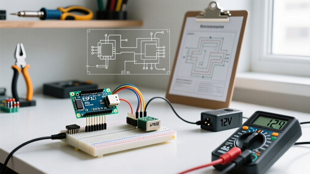
Critical Warning: Never connect the buck converter to the Arduino until the output voltage is verified.
- Connect the 12V PSU to the Input terminals of the MP1584EN buck converter.
- Using a digital multimeter, probe the Output terminals.
- Turn the small brass trimming potentiometer counter-clockwise until the multimeter reads exactly 5.00V to 5.10V.
- Apply a drop of clear nail polish or hot glue over the potentiometer to prevent vibration from altering the voltage setting during deployment.
Step 3: Wiring the Microcontroller
Instead of using the Arduino's DC barrel jack, you will inject the regulated 5V directly into the board's 5V pin.
- Connect the Buck Converter VOUT+ to the Arduino 5V pin.
- Connect the Buck Converter VOUT- to the Arduino GND pin.
- Connect your high-draw peripherals (motors, relay modules, LED strips) directly to the 12V rail and the Buck Converter's input, ensuring the microcontroller only handles logic-level switching via MOSFETs or optocouplers.
Edge Cases and Failure Modes in 12V Systems
When migrating to an Arduino power supply 12V setup, makers frequently encounter specific failure modes that do not exist in low-voltage USB setups. According to Texas Instruments' power management design guidelines, managing transient voltages is critical in mixed-voltage environments.
1. Inductive Kickback (Flyback Voltage)
If your 12V rail powers relays, solenoids, or DC motors, switching these loads off causes the collapsing magnetic field to generate a massive reverse voltage spike (sometimes exceeding 50V). If your 12V and 5V grounds are shared, this spike can back-feed through the ground plane and instantly destroy the ATmega328P or the buck converter IC.
The Fix: Always place a flyback diode (e.g., 1N4007) in reverse parallel across any inductive load. For heavy DC motors, use an RC snubber network.
2. Ground Loops and Noise
High-current 12V devices switching on and off will introduce noise into the shared ground line, causing the Arduino's ADC (Analog-to-Digital Converter) to return erratic sensor readings.
The Fix: Implement a "Star Ground" topology. Run a dedicated ground wire from the buck converter's negative terminal to the Arduino, and separate ground wires to your 12V loads. Do not daisy-chain the ground connections.
3. Reverse Polarity Catastrophe
Injecting 5V into the Arduino's 5V pin bypasses the board's onboard reverse-polarity protection diode (which is only present on the barrel jack and USB lines). If you accidentally swap VCC and GND, the microcontroller will be destroyed instantly.
The Fix: Use polarized connectors (like JST-XH or Molex Micro-Fit) that physically prevent reverse insertion, and add a Schottky diode on the 5V output line of your custom wiring harness.
Frequently Asked Questions (FAQ)
Can I power the Arduino Uno R4 WiFi with this 12V buck method?
Yes, but with caution. The Uno R4 WiFi requires a stable 5V input. Because the R4 lacks the robust thermal mass of older boards, injecting exactly 5.0V via the 5V pin is ideal. Do not exceed 5.2V, as the RA4M1 ARM Cortex-M4 processor is highly sensitive to overvoltage conditions.
Do I still need the Arduino's onboard 5V pin if I use a buck converter?
When using the buck converter method, the Arduino's 5V pin becomes an input rather than an output. You can still use it to power low-draw 5V sensors (like an I2C OLED display or BME280), but keep the total draw on that specific pin under 800mA to avoid melting the PCB trace.
What if my project requires both 12V and 3.3V?
Do not rely on the Arduino's onboard 3.3V regulator for high-draw 3.3V peripherals (like ESP8266 modules or SD card adapters). Instead, add a secondary 3.3V LDO (like the AMS1117-3.3) or a secondary buck converter tapped off the main 12V rail to ensure clean, isolated power delivery.