
Why Choose a Local Arduino Home Control Architecture?
In 2026, the smart home landscape is increasingly fragmented by cloud server shutdowns, subscription paywalls, and privacy concerns. When a manufacturer discontinues a cloud service, your expensive smart switches become bricks. Building a local arduino home control network circumvents these issues entirely. By leveraging the ESP32 microcontroller and the MQTT protocol, you can achieve sub-50ms latency, total data privacy, and complete independence from external internet connectivity.
This tutorial provides a comprehensive, professional-grade guide to building a 4-channel relay controller for lighting or HVAC dampers. We will cover hardware selection, avoiding common ESP32 boot-strapping traps, MQTT broker configuration, and robust C++ firmware design.
Required Hardware and Bill of Materials (BOM)
To ensure long-term reliability, avoid cheap, unbranded clone boards. The following components represent a robust, production-ready BOM for a single 4-gang wall switch node.
| Component | Specific Model / Specification | Approx. 2026 Cost | Purpose |
|---|---|---|---|
| Microcontroller | Espressif ESP32-WROOM-32U (DevKitC V4) | $6.50 | Wi-Fi & MQTT processing |
| Relay Module | 5V 4-Channel Optocoupler Isolated Relay | $4.20 | Switching mains/DC loads safely |
| Power Supply | Hi-Link HLK-PM01 5V 600mA AC-DC Buck | $2.80 | Step-down 120V/240V AC to 5V DC |
| Enclosure | Carlon B225R 2-Gang Old Work Box | $3.10 | UL-listed mains housing |
| Wiring | 22 AWG Silicone Wire & Wago 221 Connectors | $8.00 | Secure, vibration-proof terminations |
Total Node Cost: ~$24.60
Step 1: Wiring the ESP32 to the Relay Module
The most common point of failure in DIY arduino home control projects is improper GPIO selection and power starvation. The ESP32 has specific "strapping pins" that dictate its boot mode. If these pins are pulled LOW or HIGH by external circuitry during boot, the MCU will hang or enter flash mode.
The Strapping Pin Trap
Avoid using GPIO 0, 2, 5, 12, and 15 for relay outputs. Instead, use the following safe output pins for a 4-channel relay module:
- Relay 1: GPIO 25
- Relay 2: GPIO 26
- Relay 3: GPIO 27
- Relay 4: GPIO 14
Power and Isolation
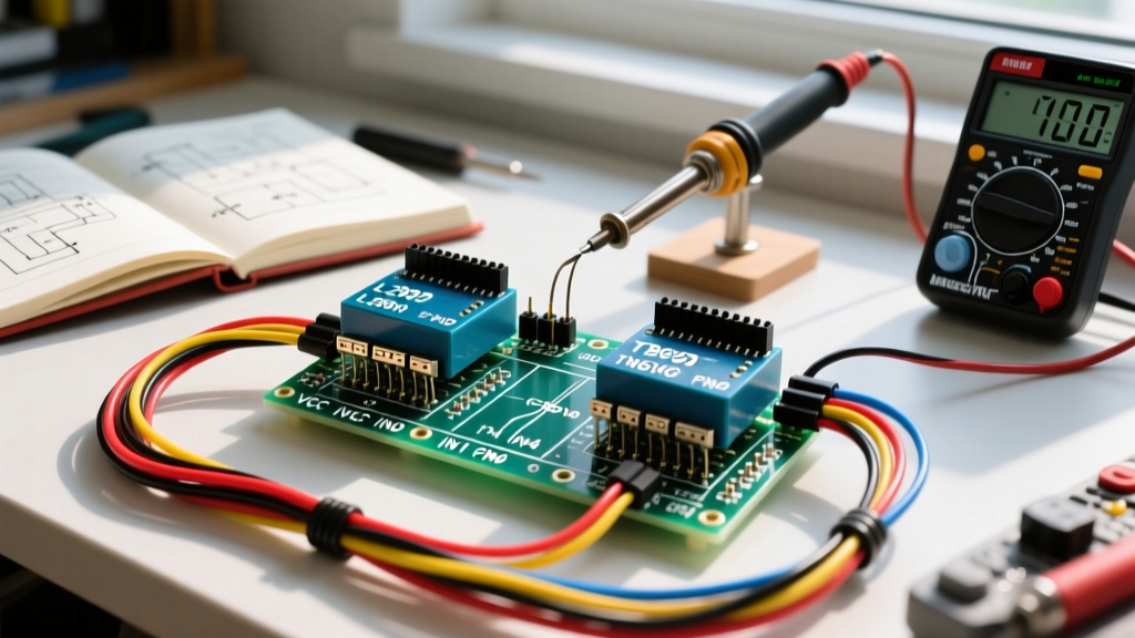
Most 5V relay modules are "Active LOW," meaning they trigger when the GPIO pin is pulled to ground. Furthermore, the relay coils draw roughly 70mA each. If all four relays engage simultaneously, the current spike can trigger the ESP32's internal brownout detector, causing a continuous reboot loop.
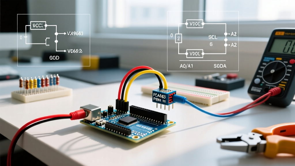
Expert Fix: Do not power the relay module directly from the ESP32's onboard 5V regulator. Wire the 5V output of the Hi-Link HLK-PM01 directly to the JD-VCC pin on the relay module (removing the VCC-JDVCC jumper). This provides optocoupler isolation and dedicated current delivery. Always place a 100µF electrolytic capacitor and a 0.1µF ceramic decoupling capacitor across the 5V and GND rails near the ESP32 to absorb transient voltage dips.
CRITICAL SAFETY WARNING: Working with 120V/240V AC mains voltage is lethal. All mains connections must be housed in UL-listed junction boxes. Never leave exposed mains terminals on a breadboard or open relay module. If you are not certified or comfortable with residential wiring, hire a licensed electrician to handle the line-voltage connections while you focus on the low-voltage Arduino home control logic.
Step 2: Setting Up the Local MQTT Broker
MQTT (Message Queuing Telemetry Transport) is the backbone of local smart home communication. We recommend running Eclipse Mosquitto on a local Raspberry Pi or a Docker container on your NAS.
- Install Mosquitto via Docker:
docker run -it -p 1883:1883 -v mosquitto_data:/mosquitto/data eclipse-mosquitto - Configure
mosquitto.confto allow local connections without passwords for testing (ensure you add ACLs and password files for production environments). - Verify the broker is listening on port 1883 using an MQTT client tool like MQTT Explorer.
For detailed MQTT integration standards, refer to the official Home Assistant MQTT Documentation, which outlines best practices for topic structuring and payload formatting.
Step 3: Writing the Arduino IDE Sketch
To handle MQTT communication, we use the PubSubClient library by Nick O'Leary. Below is a robust, production-ready sketch that handles Wi-Fi reconnection, MQTT keep-alive pings, and safe relay state initialization.
#include <WiFi.h>
#include <PubSubClient.h>

const char* ssid = "YourNetworkSSID";
const char* password = "YourNetworkPassword";
const char* mqtt_server = "192.168.1.50";

WiFiClient espClient;
PubSubClient client(espClient);

const int relayPins[] = {25, 26, 27, 14};
const int numRelays = 4;

void setup_wifi() {
  delay(10);
  WiFi.mode(WIFI_STA);
  WiFi.begin(ssid, password);
  while (WiFi.status() != WL_CONNECTED) {
    delay(500);
  }
  WiFi.setAutoReconnect(true);
}

void callback(char* topic, byte* payload, unsigned int length) {
  String msg = "";
  for (int i = 0; i < length; i++) {
    msg += (char)payload[i];
  }

  // Parse topic to determine which relay to switch
  if (String(topic) == "home/livingroom/relay1/set") {
    digitalWrite(relayPins[0], (msg == "ON") ? LOW : HIGH); // Active LOW
    client.publish("home/livingroom/relay1/state", msg.c_str());
  }
  // Repeat for other relays...
}

void reconnect() {
  while (!client.connected()) {
    if (client.connect("ESP32_HomeControl_Node1")) {
      client.subscribe("home/livingroom/relay1/set");
      // Subscribe to other topics
    } else {
      delay(5000);
    }
  }
}

void setup() {
  // CRITICAL: Set pins HIGH before setting as OUTPUT to prevent boot chatter
  for (int i = 0; i < numRelays; i++) {
    digitalWrite(relayPins[i], HIGH);
    pinMode(relayPins[i], OUTPUT);
  }

  setup_wifi();
  client.setServer(mqtt_server, 1883);
  client.setKeepAlive(60);
  client.setCallback(callback);
}

void loop() {
  if (!client.connected()) {
    reconnect();
  }
  client.loop();
}
Code Architecture Notes
Notice the setKeepAlive(60) parameter. This sends a PINGREQ packet every 60 seconds. If your router aggressively drops idle TCP connections, increasing this to 120 seconds can prevent silent MQTT disconnects. Furthermore, setting the pins HIGH before declaring them as OUTPUT in the setup() function is mandatory for Active LOW relay modules to prevent lights from flashing during the ESP32 boot sequence.
Step 4: Integration with Home Assistant
Once your ESP32 is publishing and subscribing to MQTT topics, you can map these to Home Assistant using the modern YAML configuration. Add the following to your configuration.yaml file:
mqtt:
  switch:
    - name: "Living Room Main Lights"
      command_topic: "home/livingroom/relay1/set"
      state_topic: "home/livingroom/relay1/state"
      payload_on: "ON"
      payload_off: "OFF"
      optimistic: false
      qos: 1
      retain: true
Setting retain: true ensures that if Home Assistant restarts, it immediately queries the broker for the last known state of the relay, keeping your dashboard perfectly synced with the physical hardware.
Troubleshooting Common Failure Modes
Even with perfect code, hardware-level edge cases can plague arduino home control deployments. Here is how to diagnose the most frequent issues:
1. Random Wi-Fi Dropouts and MQTT Disconnects
Symptom: The ESP32 loses connection every few hours, requiring a manual reset.
Root Cause: 2.4GHz RF interference from nearby USB 3.0 hubs or microwaves, combined with an inadequate PCB antenna.
Solution: Switch to an ESP32 model with an external IPEX/U.FL antenna connector (like the ESP32-WROOM-32U) and mount a 2.4GHz dipole antenna outside the metal junction box. Ensure your Wi-Fi router is set to a static channel (1, 6, or 11) rather than "Auto".
2. Relay Chatter or "Machine Gun" Clicking on Boot
Symptom: Relays rapidly click on and off for 2 seconds when power is applied.
Root Cause: The ESP32 outputs float during the bootloader phase before the sketch initializes the GPIO pins.
Solution: Solder 10kΩ pull-up resistors between each GPIO control pin and the 3.3V rail. This physically holds the pins HIGH until the software takes over.
3. Brownout Detector Triggering
Symptom: Serial monitor outputs rst:0xc (SW_CPU_RESET),boot:0x13 or Brownout detector was triggered when multiple relays click.
Root Cause: Voltage sag on the 5V rail dropping below the ESP32's 2.4V internal logic threshold.
Solution: Upgrade the AC-DC buck converter to a 5V 1A model (like the HLK-PM03) and verify that the trace width on your custom PCB or the gauge of your jumper wires is sufficient to handle the inrush current of the relay coils.
Final Thoughts on System Longevity
Building a local arduino home control network requires an upfront investment in time and electrical safety practices, but the payoff is a resilient, lightning-fast smart home that you truly own. By respecting ESP32 hardware quirks, isolating your power rails, and utilizing MQTT retain flags, your system will operate flawlessly for years without relying on external cloud servers. For deeper insights into ESP32 hardware design and strapping pin configurations, consult the Espressif Hardware Design Guidelines.