
The Golden Rule of Arduino to Motor Connections
If you are learning how to connect an Arduino to motor terminals, the very first rule of embedded electronics is absolute: never wire a DC motor directly to an Arduino I/O pin. Whether you are using a classic Arduino Uno R3 (ATmega328P) or the modern Uno R4 Minima (Renesas RA4M1), the microcontroller pins are designed for logic signaling, not power delivery.
A standard Arduino I/O pin can safely source or sink about 20mA of current (with an absolute maximum limit of 40mA before risking permanent silicon damage). Conversely, even a small 130-size hobby DC motor requires between 150mA and 500mA to run under normal loads, and can spike to over 1.5A during a stall condition. Furthermore, motors are inductive loads. When you cut power to a spinning motor, the collapsing magnetic field generates a reverse voltage spike (back-EMF) that can instantly fry your microcontroller's internal logic gates.
To bridge the gap between low-power logic and high-power actuation, you must use a motor driver IC. This guide details the modern, efficient approach to wiring an Arduino to motor drivers in 2026, focusing on MOSFET-based architectures that have largely replaced older, inefficient bipolar junction transistor (BJT) designs.
Choosing the Right Motor Driver (2026 Hardware Matrix)
For years, the L298N was the default choice for beginners. However, its BJT-based H-bridge design results in a massive voltage drop (up to 2V) and significant heat generation. Today, MOSFET-based drivers offer superior efficiency, compact footprints, and better thermal performance. Below is a comparison of the most reliable drivers for Arduino-to-motor projects.
| Driver IC | Topology | Continuous Current | Peak Current | Voltage Drop | 2026 Avg. Price |
|---|---|---|---|---|---|
| TB6612FNG | MOSFET | 1.2A per channel | 3.2A (single) | ~0.5V | $5.00 - $7.00 |
| DRV8833 | MOSFET | 1.5A per channel | 2.0A | ~0.4V | $3.50 - $5.00 |
| L298N | BJT | 2.0A per channel | 3.0A | ~1.5V - 2.0V | $2.50 - $4.00 |
| BTS7960 | MOSFET (High Power) | 27A per channel | 43A | ~0.1V | $12.00 - $18.00 |
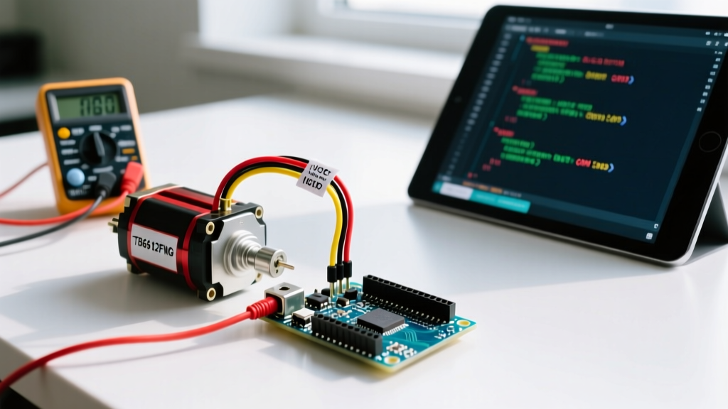
For standard 3V to 12V robotic platforms, the TB6612FNG Dual Motor Driver Carrier remains the gold standard for hobbyists and prototypers. It handles PWM frequencies up to 100kHz efficiently and requires minimal external components.
Step-by-Step Wiring: Arduino to TB6612FNG Motor Driver
When wiring your Arduino to the TB6612FNG, you must manage two separate power domains: the logic voltage (VCC) and the motor voltage (VM). Mixing these up is a common cause of dead driver boards.
1. Logic and Power Connections
- VCC: Connect to the Arduino's 5V pin. This powers the internal logic of the driver IC.
- VM: Connect to your external motor power supply positive terminal (e.g., a 6V or 12V battery pack).
- GND: Crucial step—connect the driver's GND pin to BOTH the Arduino GND and the external power supply GND. A shared ground reference is mandatory for the PWM signals to be read correctly.
- STBY (Standby): Connect directly to the Arduino 5V pin. Pulling this HIGH enables the driver; leaving it floating or LOW puts the IC to sleep.
2. Signal and PWM Connections
For Motor A, connect the following:
- PWMA: Connect to an Arduino hardware PWM pin (e.g., Pin 5). This dictates the motor speed via duty cycle.
- AIN1 & AIN2: Connect to standard digital pins (e.g., Pin 4 and Pin 7). These control the H-bridge direction (Forward, Reverse, Brake, Coast).
3. Motor Output
- AO1 & AO2: Connect directly to the two terminals of your DC motor. Polarity does not matter initially; if the motor spins the wrong way, simply swap these two wires.
Power Supply Sizing and Stall Current Math
A frequent point of failure in Arduino-to-motor projects is undersizing the power supply. You cannot size your battery or bench supply based on the motor's running current; you must size it for the stall current.
Engineering Rule of Thumb: When a motor is starting from a dead stop, or when it jams against a physical obstacle, it draws stall current. This can be 5 to 10 times higher than the nominal free-run current.
Calculation Example:
Suppose you are using two 12V DC gear motors. The datasheet lists a free-run current of 300mA and a stall current of 1.8A. If both motors start simultaneously or stall at the same time, your power supply must deliver:
1.8A (Motor 1) + 1.8A (Motor 2) = 3.6A continuous capability.
Therefore, a standard 9V alkaline battery (which struggles to supply more than 500mA before its voltage sags) will cause the Arduino to brownout and reset. Instead, use a 3S LiPo battery (11.1V) capable of 20C discharge, or a 12V 5A sealed lead-acid (SLA) battery. For bench testing, a Mean Well LRS-50-12 enclosed switching power supply provides rock-solid, ripple-free current.
Essential Protection Components
While modern drivers like the Texas Instruments DRV8833 and the TB6612FNG include internal freewheeling diodes to handle back-EMF, relying solely on them in harsh environments is poor practice. Add these passive components to ensure longevity:
- Schottky Flyback Diodes (1N5819): Solder these across the motor terminals (cathode to positive, anode to negative). Schottky diodes have a faster recovery time and lower forward voltage drop than standard 1N4007 rectifier diodes, clamping inductive spikes more effectively.
- Decoupling Capacitors (100nF MLCC): Solder a 100nF (0.1µF) ceramic capacitor directly across the physical motor terminals. This suppresses high-frequency brush noise that can otherwise travel back through the power rails and corrupt Arduino I2C or SPI sensor data.
- Bulk Electrolytic Capacitor (470µF - 1000µF): Place this on the main power distribution board near the motor driver's VM input. It acts as a local energy reservoir to handle sudden current demands during motor startup, preventing voltage dips that trigger the Arduino's undervoltage lockout.
C++ Control Code for PWM and Direction
Controlling the motor requires manipulating the direction pins and applying a PWM signal to the speed pin. The analogWrite() function in Arduino generates a default 490Hz PWM signal, which is perfectly suited for most DC motors without causing excessive audible whine. For a deeper understanding of how microcontrollers generate these signals, refer to the official Arduino PWM foundations guide.
// Pin Definitions for Motor A
const int PWMA = 5;   // PWM Speed Control
const int AIN1 = 4;   // Direction Pin 1
const int AIN2 = 7;   // Direction Pin 2
const int STBY = 8;   // Standby Pin

void setup() {
  pinMode(PWMA, OUTPUT);
  pinMode(AIN1, OUTPUT);
  pinMode(AIN2, OUTPUT);
  pinMode(STBY, OUTPUT);

  digitalWrite(STBY, HIGH); // Enable the driver
}

void loop() {
  // Move Forward at 75% speed
  setMotor(1, 190);
  delay(2000);

  // Hard Brake
  brakeMotor();
  delay(500);

  // Move Reverse at 50% speed
  setMotor(-1, 127);
  delay(2000);

  // Coast (Stop)
  coastMotor();
  delay(2000);
}

// Direction: 1 = Forward, -1 = Reverse, 0 = Coast
// Speed: 0 to 255
void setMotor(int direction, int speed) {
  if (direction == 1) {
    digitalWrite(AIN1, HIGH);
    digitalWrite(AIN2, LOW);
  } else if (direction == -1) {
    digitalWrite(AIN1, LOW);
    digitalWrite(AIN2, HIGH);
  } else {
    digitalWrite(AIN1, LOW);
    digitalWrite(AIN2, LOW);
  }
  analogWrite(PWMA, speed);
}

void brakeMotor() {
  digitalWrite(AIN1, HIGH);
  digitalWrite(AIN2, HIGH);
  analogWrite(PWMA, 0);
}

void coastMotor() {
  digitalWrite(AIN1, LOW);
  digitalWrite(AIN2, LOW);
  analogWrite(PWMA, 0);
}
Advanced Troubleshooting and Edge Cases
Even with perfect wiring, real-world physics can introduce anomalies. Here is how to diagnose the most common Arduino-to-motor integration failures.
1. The 'Twitching' Motor and Arduino Resets
Symptom: When the motor is commanded to start, it twitches slightly, and the Arduino's onboard LED flickers or the board resets entirely.
Diagnosis: This is a classic brownout. The motor's inrush current is dragging the shared 5V logic rail down below the microcontroller's minimum operating threshold (typically 2.7V for the ATmega328P).
Solution: You are likely powering the Arduino and the motor from the same linear regulator, or your battery's internal resistance is too high. Separate the logic power from the motor power using two distinct voltage regulators, or upgrade to a high-discharge LiPo battery.
2. High-Pitched Whining from the Motor
Symptom: The motor operates, but emits an annoying, audible high-frequency squeal, especially at low PWM speeds.
Diagnosis: The default Arduino PWM frequency on pins 5 and 6 is 980Hz, while pins 3, 9, 10, and 11 operate at 490Hz. The magnetostriction in the motor's core and the physical vibration of the windings are resonating at these frequencies.
Solution: Shift the PWM frequency above the human hearing range (20kHz). You can achieve this by modifying the Timer/Counter registers in the Arduino setup function. For example, setting Timer 0 to Fast PWM mode can push the frequency to ~31kHz, rendering the motor acoustically silent.
3. Erratic Sensor Readings (I2C/SPI Bus Corruption)
Symptom: Your OLED display glitches, or your IMU (like the BNO085) drops off the I2C bus whenever the motors change speed.
Diagnosis: Brushed DC motors are essentially broadband RF noise generators. The carbon brushes sparking against the commutator inject high-frequency electrical noise directly into your power and ground planes.
Solution: Ensure the 100nF capacitors are soldered directly to the motor casing terminals. If the issue persists, implement galvanic isolation using digital isolators (like the ISO1540) on your I2C lines, or route your sensor ground through a star-topology grounding scheme to prevent motor return currents from flowing under the microcontroller.
By respecting the electrical boundaries between low-voltage logic and high-current inductive loads, your Arduino-to-motor projects will transition from unreliable prototypes to robust, field-ready machines.