
The MAX7219 Arduino LED Matrix: Beyond the Basics
The MAX7219 is a legendary serially interfaced LED display driver. When paired with an 8x8 LED matrix (commonly sold as the FC-112 module), it provides a low-cost, high-visibility output for microcontrollers. However, as makers push these displays into complex daisy-chained arrays and high-speed animations in 2026, standard beginner tutorials fall short. They ignore critical power delivery bottlenecks and SPI signal integrity issues that cause flickering, thermal shutdowns, and garbage data on screen.
This advanced how-to tutorial covers the exact hardware architecture, power math, and MD_MAX72XX library implementation required to build a rock-solid MAX7219 Arduino display.
Hardware BOM & 2026 Pricing
Before wiring, ensure you have the correct components. Generic MAX7219CNG DIP chips are largely obsolete for DIY; the surface-mount MAX7219CWG mounted on FC-112 PCBs is the current standard.
| Component | Specification | Est. Cost (2026) |
|---|---|---|
| FC-112 Matrix Module | MAX7219CWG + 1088AS 8x8 Matrix | $2.50 - $3.80 |
| Microcontroller | Arduino Uno R4 Minima or Nano Every | $14.00 - $18.00 |
| Power Supply | 5V 3A Buck Converter (MP1584EN) | $2.20 |
| Wiring | 22 AWG Silicone Wire & 100nF Decoupling Caps | $5.00 |
The #1 Failure Mode: Power Architecture
⚠️ CRITICAL WARNING: Never power a daisy-chained MAX7219 array from the Arduino 5V pin.A single 8x8 matrix with a standard 10kΩ $R_{SET}$ resistor draws roughly 330mA at peak brightness (all LEDs illuminated). If you daisy-chain four modules, peak current exceeds 1.3A. The Arduino Uno's onboard linear regulator will overheat, trigger thermal shutdown, or permanently fail. Always inject 5V power directly into the display array's VCC/GND rails using an external buck converter.
Understanding the $R_{SET}$ Resistor
According to the Analog Devices MAX7219 Datasheet, the segment current is programmed via a single resistor connected from V+ to ISET. Most FC-112 modules ship with a 10kΩ surface-mount resistor (marked '103'). This limits segment current to ~4.7mA. Because the MAX7219 multiplexes at a 100:1 duty cycle ratio, the peak current per segment is 470mA, but the average current is safe. If you buy custom boards and want higher brightness, dropping $R_{SET}$ to 4.7kΩ doubles the brightness but requires robust thermal management.
Step-by-Step Wiring Guide
The MAX7219 communicates via a proprietary 3-wire SPI-like protocol. While it resembles standard SPI, it does not strictly adhere to the SPI mode 0/3 clock phase rules, which is why bit-banging or specialized hardware SPI libraries are required.
1. Signal Connections (Arduino Uno R4 / Nano)
- VCC: Connect to external 5V Buck Converter output.
- GND: Connect to external Buck Converter GND and Arduino GND (Common ground is mandatory for SPI logic reference).
- DIN (Data In): Connect to Arduino MOSI (Pin 11 on Uno, Pin 11 on Nano).
- CS (Chip Select / LOAD): Connect to Arduino SS (Pin 10).
- CLK (Clock): Connect to Arduino SCK (Pin 13).
2. Daisy-Chaining Multiple Modules
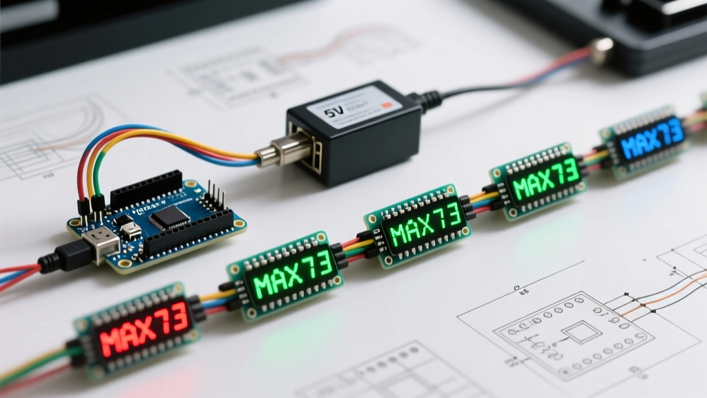
To chain modules, connect the DOUT (Data Out) of the first module to the DIN of the second module. VCC, GND, CS, and CLK are wired in parallel across all modules.
💡 Pro-Tip: SPI Signal IntegrityWhen chaining more than four modules, the physical length of the CLK and MOSI wires increases. Unshielded jumper wires longer than 15cm act as antennas, picking up EMI and causing 'ghosting' or random pixels. For long arrays, use twisted-pair wiring for CLK/GND and MOSI/GND, or add a 74HC14 hex inverter to buffer and clean the SPI signals.
Software: Why MD_MAX72XX is the 2026 Standard
Historically, makers used the LedControl library. However, for modern applications requiring scrolling text, sprite animations, and hardware SPI acceleration, MajicDesigns' MD_MAX72XX library is the undisputed standard. It natively supports hardware SPI, drastically reducing CPU overhead on the Arduino and preventing animation stuttering.
Library Installation
- Open the Arduino IDE and navigate to Sketch > Include Library > Manage Libraries.
- Search for
MD_MAX72XXby MajicDesigns and install the latest version. - Install the dependency
MD_Parolaif you intend to use advanced text scrolling and alignment effects.
Core Implementation Code
Below is a production-ready initialization sketch for a 4-module daisy-chained array using Hardware SPI. For deeper API documentation, refer to the official MD_MAX72XX GitHub Pages.
#include <MD_MAX72xx.h>
#include <SPI.h>

// Hardware SPI pins (Arduino Uno/Nano)
#define CS_PIN  10
#define MAX_DEVICES 4

// Define the hardware type (FC-112 is usually GENERIC_HW or FC16_HW)
#define HARDWARE_TYPE MD_MAX72XX::FC16_HW

MD_MAX72XX mx = MD_MAX72XX(HARDWARE_TYPE, CS_PIN, MAX_DEVICES);

void setup() {
  // Initialize Hardware SPI at 10MHz
  SPI.begin();
  mx.begin();

  // Set initial intensity (0-15)
  mx.control(MD_MAX72XX::INTENSITY, 4);
  mx.clear();

  // Draw a simple diagonal line across all 4 matrices
  for (uint8_t i = 0; i < MAX_DEVICES * 8; i++) {
    mx.setPoint(i % 8, i, true);
  }
}

void loop() {
  // Animation logic goes here
}
Troubleshooting Matrix: Edge Cases & Fixes
Even with perfect wiring, environmental and hardware variances can cause issues. Use this diagnostic matrix to resolve common anomalies.
| Symptom | Root Cause | Engineering Fix |
|---|---|---|
| Display flickers during animation | Voltage sag on breadboard power rails due to high transient current. | Solder 100µF electrolytic and 100nF ceramic decoupling capacitors directly across the VCC/GND pins of the first and last MAX7219 modules. |
| Random 'garbage' pixels appear | Floating CS pin during Arduino boot, or SPI clock noise. | Add a 10kΩ pull-up resistor between CS and VCC. Ensure common ground between Arduino and external power supply. |
| Right-most modules are dimmer | Voltage drop across thin PCB traces in long daisy chains. | Inject 5V power at both ends of the display array (parallel power injection) rather than just the first module. |
| Text is backwards or scrambled | Incorrect hardware definition in software. | Change MD_MAX72XX::FC16_HW to GENERIC_HW or ICSTATION_HW depending on the physical PCB layout of your matrix. |
Advanced Integration: ESP32 and 3.3V Logic
If you are migrating your MAX7219 array from an Arduino to an ESP32 for Wi-Fi connected clocks or stock tickers, you face a logic level mismatch. The ESP32 operates at 3.3V, while the MAX7219 requires 5V logic for reliable HIGH state recognition on the DIN and CLK pins.
While some modern FC-112 clones will trigger at 3.3V, relying on this is poor engineering practice. Use a bidirectional logic level shifter (like the BSS138 MOSFET-based modules) or a dedicated 74HCT245 octal bus transceiver powered at 5V to shift the ESP32's 3.3V SPI signals to 5V. For more on microcontroller SPI specifications, consult the Arduino SPI Reference Documentation.
Conclusion
Mastering the MAX7219 with Arduino requires moving beyond simple copy-paste wiring diagrams. By calculating your power requirements, injecting external 5V current, managing SPI signal integrity, and leveraging the hardware-accelerated MD_MAX72XX library, you can build commercial-grade LED matrix displays that run flawlessly for years.