
Using a sliding potentiometer to control LED brightness via an Arduino is a foundational skill in interactive electronics, custom MIDI controller builds, and stage lighting prototypes. Unlike rotary pots, slide potentiometers (often called faders) offer a linear visual representation of the parameter being adjusted, making them ideal for lighting desks, audio mixers, and motorized control surfaces. In 2026, the availability of high-quality, low-profile slide pots from manufacturers like Bourns and Alps has made them more accessible than ever, with standard 60mm travel models costing between $1.50 and $3.00. This quick reference guide and FAQ addresses the most common hardware, software, and troubleshooting questions regarding sliding potentiometer control LED Arduino projects, ensuring your PWM dimming is buttery smooth and free of ADC noise.
Quick Reference: Sliding Potentiometer Specifications
Before wiring your circuit, verify that your slide potentiometer matches the requirements of your microcontroller and LED driver. Below is a comparison of common fader types used in maker projects.
| Parameter | Standard DIY Slide Pot (e.g., Bourns PTA6043) | Audio/Mixing Fader (e.g., Alps RS60N) | Motorized Slide Pot (e.g., Bourns PTB0143) |
|---|---|---|---|
| Resistance | 10kΩ (Linear) | 10kΩ to 100kΩ (Audio/Linear) | 10kΩ (Linear) |
| Travel Length | 45mm, 60mm, 100mm | 60mm, 100mm | 60mm, 100mm |
| Power Rating | 0.25W | 0.1W to 0.25W | 0.5W |
| Typical Price | $1.50 - $3.00 | $4.00 - $8.00 | $14.00 - $22.00 |
Frequently Asked Questions (FAQ)
Q1: How do I wire a sliding potentiometer to an Arduino for LED control?
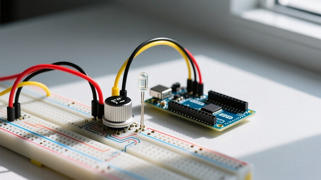
A slide potentiometer functions as a variable voltage divider. It has three primary pins: CCW (Counter-Clockwise/Bottom), Wiper (Middle), and CW (Clockwise/Top). To interface with an Arduino Uno or Nano:
- Pin 1 (CCW/GND): Connect to the Arduino GND pin.
- Pin 2 (Wiper): Connect to an analog input pin (e.g., A0). This is the variable signal.
- Pin 3 (CW/VCC): Connect to the Arduino 5V pin.
For the LED, connect the anode to a PWM-capable digital pin (e.g., Pin 9) through a 220Ω current-limiting resistor, and the cathode to GND. Never wire the slide pot directly in series with a high-power LED as a rheostat; standard 0.25W pots will overheat and fail. Always use the wiper as a signal input to the microcontroller, which then drives the LED via PWM or a dedicated MOSFET driver. For a deeper understanding of how the wiper divides voltage, refer to SparkFun's guide on voltage dividers.
Q2: Why is my LED flickering or jumping when I move the slider?
Flickering or 'jitter' in sliding potentiometer control LED Arduino projects is almost always caused by electromagnetic interference (EMI) or a floating wiper. The Arduino's 10-bit ADC is highly sensitive to high-frequency noise from USB lines or nearby switching power supplies. When the ADC samples this noise, the `analogRead()` value fluctuates rapidly, causing the PWM output to stutter.
Pro-Tip: The Hardware RC Filter Fix
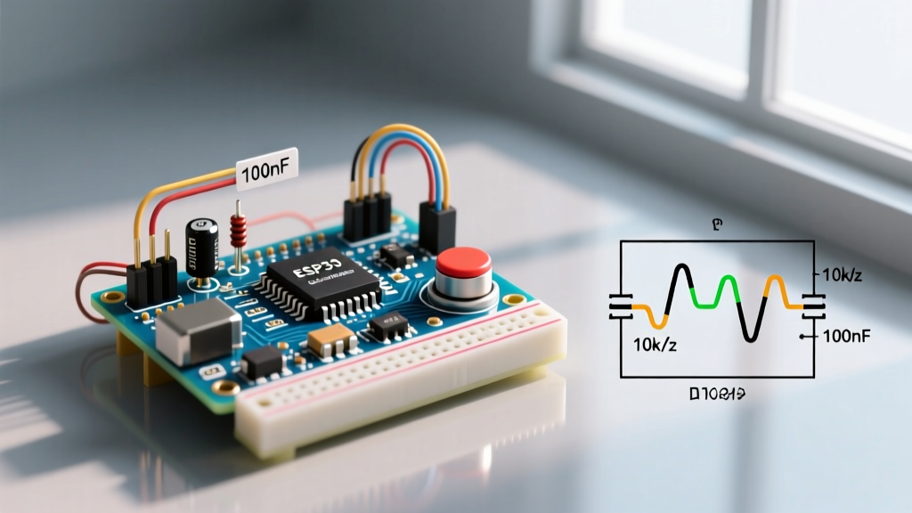
Solder a 100nF (0.1µF) ceramic capacitor directly between the Wiper pin and GND. This creates a low-pass RC filter. With a 10kΩ pot, the cutoff frequency is roughly 159Hz, and the time constant (τ = RC) is 1ms. This filters out high-frequency EMI without introducing any perceptible physical lag when moving the slider, resulting in perfectly stable ADC readings.
Q3: What is the best code for smooth sliding potentiometer control LED Arduino dimming?
The most efficient approach uses the `map()` function to scale the 10-bit ADC reading (0-1023) to the 8-bit PWM range (0-255). Below is the optimized, non-blocking code structure for 2026 standard practices:
// Sliding Potentiometer LED Control
const int slidePot = A0;
const int ledPin = 9;

// Variables for smoothing (optional but recommended)
int smoothedValue = 0;

void setup() {
  pinMode(ledPin, OUTPUT);
  Serial.begin(9600);
}

void loop() {
  // Read the raw ADC value
  int rawValue = analogRead(slidePot);

  // Apply a simple exponential moving average for software smoothing
  smoothedValue = (smoothedValue * 0.8) + (rawValue * 0.2);

  // Map the smoothed 10-bit value to 8-bit PWM
  int pwmValue = map(smoothedValue, 0, 1023, 0, 255);
  pwmValue = constrain(pwmValue, 0, 255);

  analogWrite(ledPin, pwmValue);

  // Small delay to stabilize ADC sampling rate
  delay(5);
}
For complete syntax details on reading analog pins, consult the official Arduino analogRead() reference.
Q4: Linear vs. Audio (Logarithmic) Taper: Which should I use for LEDs?
Slide potentiometers come in different tapers. A Linear taper (B10k) outputs voltage proportionally to physical travel (e.g., 50% travel = 2.5V). An Audio taper (A10k) follows a logarithmic curve. Because the human eye perceives light intensity logarithmically (similar to how ears perceive sound), a linear potentiometer will make the LED appear to jump from 'off' to 'blindingly bright' in the first 20% of the physical slide, with the remaining 80% of the travel showing barely noticeable changes. If you want perceptual linearity—where moving the slider 50% physically results in the LED appearing 50% as bright to the human eye—you should either use an Audio taper slide pot or apply a gamma-correction lookup table in your Arduino code.
Troubleshooting Matrix
Use this quick-reference matrix to diagnose common hardware and software faults in your fader circuit.
| Symptom | Root Cause | Hardware / Software Fix |
|---|---|---|
| LED stays at max brightness regardless of slider position. | Wiper and VCC pins are shorted, or wiper is disconnected (floating high). | Check continuity with a multimeter. Ensure Pin 2 (Wiper) is connected to A0. |
| LED is completely off, but Serial Monitor shows changing values. | LED connected to a non-PWM digital pin (e.g., Pin 12 on Uno). | Move LED anode to a PWM pin marked with a tilde (~), such as Pin 9, 10, or 11. |
| Slider feels physically 'scratchy' or values drop to zero randomly. | Carbon track inside the pot is dirty or oxidized. | Spray contact cleaner (e.g., DeoxIT F5) into the fader slot and cycle the slider 20 times. |
| Slider only reads values between 500 and 1023. | GND pin is not connected, causing the voltage divider to float. | Verify the CCW pin has a solid, low-resistance path to the Arduino GND. |
Advanced Considerations: ADC Resolution and Perceptual Linearity
If you are upgrading from an Arduino Uno (ATmega328P) to an ESP32-S3 for a high-end lighting controller in 2026, be aware of the differences in Analog-to-Digital Converters. The ESP32-S3 features a 12-bit SAR ADC (0-4095 steps), which theoretically provides much finer control over LED dimming than the Uno's 10-bit ADC. However, ESP32 ADCs are notorious for non-linearities at the extreme ends of the voltage spectrum (near 0V and 3.3V).
To achieve true 12-bit precision for professional sliding potentiometer control LED Arduino setups, consider bypassing the internal ADC entirely. Using an external SPI ADC, such as the Microchip MCP3208 (12-bit, 8-channel), guarantees linear, noise-free readings across the entire physical travel of the slide pot. Furthermore, when sourcing components, always verify the mechanical travel length matches your enclosure design. The Bourns slide potentiometer catalog provides exact CAD footprints for 45mm, 60mm, and 100mm travel variants, ensuring your 3D-printed or CNC-machined faceplates align perfectly with the fader cap.