
The 2026 Diagnostic Matrix: Motor Drive Arduino Failures
Interfacing DC motors with microcontrollers seems straightforward in simulation, but real-world physics quickly exposes flaws in power delivery and signal integrity. Whether you are building a rover or an automated actuator, a failing motor drive Arduino setup usually stems from one of five hardware bottlenecks. While MOSFET-based drivers have largely replaced older bipolar junction transistor (BJT) chips in professional 2026 designs, legacy boards like the L298N remain ubiquitous in maker bins, bringing their own unique failure modes.
Before tearing apart your breadboard, cross-reference your symptoms with the diagnostic matrix below to isolate the root cause of your motor drive Arduino errors.
| Symptom | Common Culprit Driver | Root Cause | Multimeter / Scope Check | Hardware Fix |
|---|---|---|---|---|
| Arduino resets when motor starts | L298N, BTS7960 | Power rail brownout / Voltage sag | 5V rail drops below 4.2V under load | Isolate logic power; add 470µF bulk capacitor |
| Motor twitches but won't spin | L298N, A4988 | Logic level mismatch (3.3V vs 5V) | Logic pins read 3.2V (below 4.5V Vih threshold) | Use 74HCT245 level shifter or pull-up resistors |
| Driver IC overheats and shuts down | DRV8833, TB6612FNG | Inductive kickback (Back-EMF) exceeding diode limits | Scope shows >15V spikes on OUT pins | Add external 1N5819 Schottky flyback diodes |
| Audible high-pitched whine from motor | Any PWM-driven H-Bridge | Default 490Hz Arduino PWM frequency | N/A (Audible) | Implement TimerOne library for 20kHz PWM |
| I2C encoders drop packets randomly | High-current drivers (>5A) | Ground loop noise corrupting logic | AC mV ripple on GND reference line | Implement star-grounding topology |
Error 1: The "Brownout" Reset Loop (Power Starvation)
The most frequently reported motor drive Arduino error is the endless reset loop. You upload your sketch, the motor attempts to start, and the Arduino instantly reboots. This is almost always a brownout caused by shared power rails and the high stall current of DC motors.
The L298N Voltage Drop Problem
The L298N uses Darlington pair BJT transistors. According to the STMicroelectronics L298N datasheet, this architecture introduces a saturation voltage drop (Vce_sat) of up to 3.2V at 2A. If you feed 7V into the L298N's motor terminal and use the onboard 5V regulator to power your Arduino Uno, a motor stall will cause the input voltage to sag. The onboard linear regulator drops out, the Arduino's 5V line falls below the ATmega328P's 4.2V brownout detection threshold, and the MCU resets.
Expert Fix: Never power a 5V Arduino from the L298N's onboard regulator if the motor draws more than 500mA. Use a separate 5V buck converter (like the LM2596 module, ~$2.50) for the Arduino, and connect the grounds. Solder a 470µF low-ESR electrolytic capacitor directly across the motor driver's main power input terminals to buffer transient current spikes.
Error 2: Logic Level Mismatches & Ghost Signals
As makers migrate to 3.3V microcontrollers like the ESP32, Arduino Due, or Raspberry Pi Pico in 2026, logic level mismatches have become a primary source of motor drive Arduino failures. Older motor drivers require a minimum High-level Input Voltage (Vih) to register a logic "1".
Diagnosing the Ghost Twitch
If your motor twitches erratically or fails to engage despite correct code, measure the voltage at the driver's IN1 and IN2 pins while the MCU outputs HIGH. The L298N requires a minimum of 2.3V to register a HIGH signal, but marginal signal integrity from long jumper wires can cause the signal to float in the undefined region between 1.5V and 2.3V. Modern MOSFET drivers like the TB6612FNG are more tolerant, but still suffer from noise.
Actionable Solutions
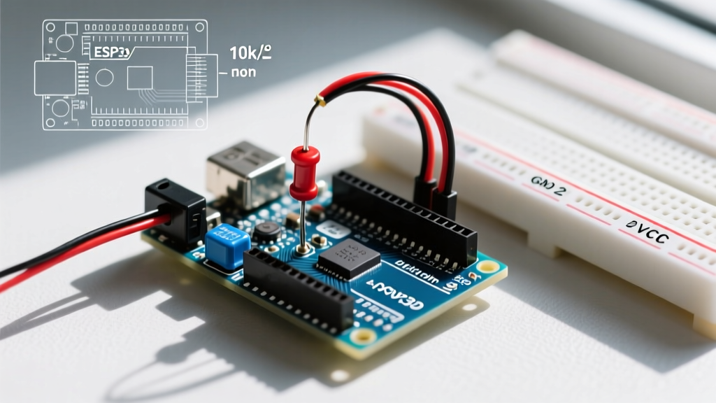
- Pull-Down Resistors: Solder 10kΩ resistors between every logic input pin and GND on your motor driver. This ensures the H-Bridge defaults to a safe "coast" or "brake" state during Arduino boot-up when GPIO pins are high-impedance.
- Level Shifters: If driving a strictly 5V logic driver from a 3.3V ESP32, use a bidirectional logic level converter (e.g., Texas Instruments TXB0108 or a cheap 4-channel MOSFET-based shifter for $1.50) to guarantee crisp 5V square waves.
Error 3: Flyback Diode Failures & H-Bridge Fry-ups
DC motors are massive inductors. When an H-Bridge abruptly cuts power to a spinning motor, the collapsing magnetic field generates a massive reverse voltage spike (Back-EMF). If this spike exceeds the breakdown voltage of the driver's internal MOSFETs, the silicon literally vaporizes.
The DRV8833 Thermal Shutdown Trap
The Texas Instruments DRV8833 is a fantastic, compact dual H-bridge (often found on $3 breakout boards). However, the TI DRV8833 datasheet notes that while it includes internal clamp diodes, they are only rated to handle typical commutation spikes. If you are driving high-inertia loads or reversing motor direction rapidly (plug-braking), the internal diodes will overheat, triggering the IC's thermal shutdown at 150°C junction temperature.
Pro-Tip for High-Inertia Loads: Bypass the internal diodes by adding four external 1N5819 Schottky diodes per motor channel. Schottky diodes have a faster reverse recovery time and a lower forward voltage drop (~0.4V) compared to standard 1N4007 rectifiers, shunting the Back-EMF safely to the VMOT rail before it can damage the IC.Error 4: PWM Frequency Jitter & Audible Whine
By default, the Arduino PWM documentation confirms that the analogWrite() function operates at approximately 490Hz (or 980Hz on pins 5 and 6 of the Uno). When applied to a motor drive Arduino circuit, this sub-1kHz frequency falls squarely in the human hearing range, causing the motor windings and the ceramic capacitors on the driver board to emit an annoying, high-pitched whine.
Fixing Timer Conflicts
To eliminate the whine, you must push the PWM frequency above 20kHz (the upper limit of human hearing). However, blindly changing Arduino hardware timers can break the delay(), millis(), and Servo libraries, which rely on Timer0.
The TimerOne Library Approach
- Install the TimerOne library via the Arduino IDE Library Manager.
- Move your motor PWM pins to Timer1-controlled pins (Pins 9 and 10 on the ATmega328P).
- Initialize the timer in your
setup()block:Timer1.initialize(50);(This sets the period to 50 microseconds, equating to exactly 20,000 Hz). - Replace
analogWrite(9, speed);withTimer1.pwm(9, speed);.
Note: The PWM resolution changes when using TimerOne. You must map your speed values from 0-255 to 0-1023 using the map() function.
Error 5: Ground Loop Noise Corrupting I2C & Serial
In advanced robotics, your motor drive Arduino setup likely includes I2C motor encoders, LiDAR sensors, or serial communication. A common, deeply frustrating error is random packet loss or I2C bus lockups that only occur when the motors are under heavy load.
The Star Grounding Topology
High-current motor return paths create millivolt-level AC ripples across the ground plane of your breadboard or PCB. If your Arduino's I2C SDA/SCL lines reference a "noisy" ground, the logic thresholds are crossed, resulting in corrupted data. To solve this, abandon daisy-chained ground wires. Instead, implement a Star Ground:
- Run a single, thick (14 AWG or lower) ground wire directly from the negative terminal of your main battery pack to a central terminal block.
- From this central block, run individual ground wires to the motor driver's high-power GND, the Arduino's GND, and the sensor array's GND.
- Use optocouplers (like the 6N137) for any serial communication lines crossing between the high-power motor domain and the low-power logic domain.
Final Diagnosis Checklist
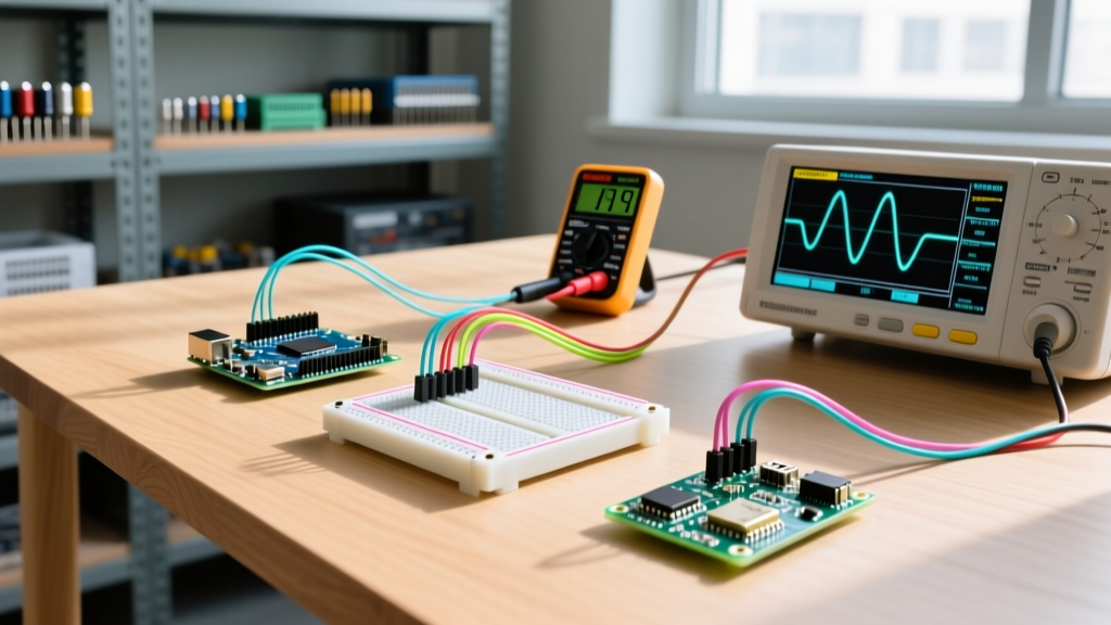
Before replacing a seemingly "dead" motor driver, verify these three physical metrics: First, check the continuity of your jumper wires—cheap Dupont connectors frequently suffer from internal crimp failures that cause intermittent voltage drops under vibration. Second, measure the actual current draw of your motor using a multimeter in series; a motor rated for 200mA free-spin might pull 3A at stall, instantly tripping the overcurrent protection on a 1.5A TB6612FNG. Finally, ensure your code includes a 50-millisecond dead-time delay when switching from FORWARD to REVERSE. Slamming an H-Bridge directly into reverse while the motor is generating forward Back-EMF causes a massive short-circuit current spike that will permanently weld the internal MOSFETs of budget driver clones.