
Why You Need a Dedicated Arduino Schematic Maker
Transitioning from a solderless breadboard to a custom Printed Circuit Board (PCB) is a rite of passage for serious electronics makers. While breadboards are excellent for initial prototyping, they suffer from parasitic capacitance, loose jumper connections, and high contact resistance that can cause microcontroller brownouts or erratic sensor readings. To design a reliable, manufacturable custom board, you need a robust Arduino schematic maker—a dedicated Electronic Design Automation (EDA) tool configured specifically for microcontroller workflows.
An Arduino schematic maker is not just a drawing tool; it is a rule-based environment that ensures your ATmega328P, SAMD21, or ESP32 circuits are electrically sound before they ever reach the PCB layout phase. In this 2026 configuration guide, we will walk through the exact setup parameters, library management strategies, and Design Rule Check (DRC) configurations for the industry's most popular EDA platforms.
2026 Schematic Maker Comparison Matrix
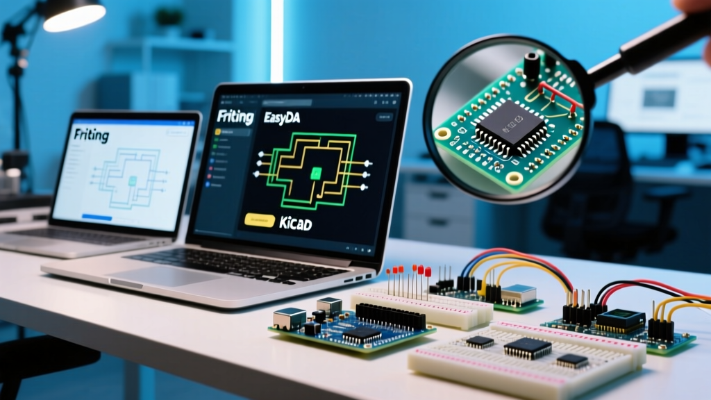
Choosing the right software depends on your project complexity, budget, and manufacturing pipeline. Below is a technical comparison of the top three platforms used by the maker community today.
| Feature | KiCad (v8/v9) | EasyEDA (Standard/Pro) | Fritzing (v1.0+) |
|---|---|---|---|
| Licensing & Cost | Open-Source (Free) | Cloud-based (Free tier / $10/mo Pro) | Paid (Starts at $8 one-time) |
| Library Management | Local, GitHub-integrated, highly customizable | Direct LCSC integration, massive cloud library | Core library only, limited custom imports |
| Design Rule Check (DRC) | Advanced, supports custom constraint managers | Standard, tied to JLCPCB manufacturing limits | Basic, often misses complex net violations |
| Best For | Complex multi-layer MCU boards, professional workflows | Quick 2-layer prototypes, direct JLCPCB ordering | Simple educational circuits, basic Arduino shields |
Step-by-Step Configuration: KiCad for ATmega328P Projects
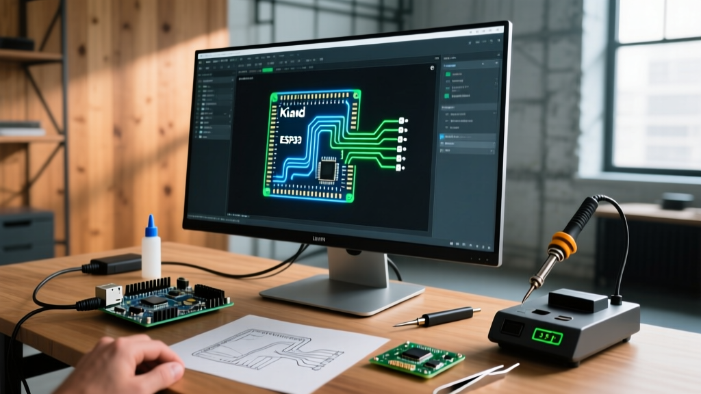
KiCad EDA remains the gold standard for open-source hardware design. However, its default configuration is generalized for all electronics. To use it effectively as an Arduino schematic maker, you must tune the environment for microcontroller-specific footprints and routing constraints.
1. Importing Official Arduino Footprints
Before placing your first component, you must integrate the official Arduino symbol and footprint libraries. Do not rely on generic ATmega symbols, as they often mislabel the SPI and I2C alternate functions.
- Download the official Arduino Hardware Libraries from their GitHub repository.
- Open KiCad's Preferences > Manage Symbol Libraries and add the downloaded
.kicad_symfile as a Global Library. - Repeat the process in Manage Footprint Libraries for the
.prettydirectories, ensuring you map the TQFP-32 (SMD) and DIP-28 (Through-hole) variants correctly.
2. Grid and Design Rule Check (DRC) Tuning
Microcontroller routing requires strict adherence to grid alignments to prevent orphaned pads and unroutable channels.
- Schematic Grid: Lock your schematic capture grid to 50 mils. This is the industry standard for pin spacing and ensures wires snap cleanly to component terminals without creating hidden broken nets.
- PCB Layout Grid: Set your component placement grid to 50 mils, but reduce your routing grid to 10 mils (or 5 mils for BGA/QFN components).
- DRC Constraints: For standard 2-layer boards manufactured by houses like JLCPCB or PCBWay in 2026, configure your net classes to a minimum trace width of 6 mils (0.15mm) and a clearance of 6 mils. For power rails (5V and GND), create a custom net class with a minimum width of 20 mils to handle the current draw of servo motors or high-brightness LED matrices.
Pro-Tip: Never use the KiCad auto-router for microcontroller boards. The auto-router does not understand signal integrity and will frequently route high-speed SPI clock lines parallel to noisy analog sensor traces, causing ADC jitter. Always route MCU critical paths manually.
Cloud-Based Configuration: EasyEDA Standard vs. Pro
If you want to bypass the friction of local library management, EasyEDA is an exceptional cloud-based Arduino schematic maker. Its killer feature is the direct integration with the LCSC component catalog, allowing you to place a symbol in your schematic and guarantee that the exact physical part is in stock and ready to be assembled via their PCBA service.
LCSC Library Mapping for Microcontrollers
When designing an Arduino-compatible board from scratch (using the raw ATmega328P-AU chip rather than a pre-made Nano module), component selection is critical.
- Open the EasyEDA Library panel and search for
ATMEGA328P-AU. - Filter by LCSC Assembled to ensure you are selecting a footprint that matches JLCPCB's basic parts list, saving you extended setup fees.
- Verify the 3D model footprint against the TQFP-32 datasheet. A common failure mode in cloud libraries is selecting a footprint with a 0.8mm pitch when the chip requires a 0.65mm pitch.
Critical Schematic Pitfalls and Edge Cases
Even with a perfectly configured Arduino schematic maker, designers frequently introduce hardware-level bugs that prevent the bootloader from flashing or cause random resets. Audit your schematic against this checklist before generating Gerbers.
The Decoupling Capacitor Rule
Every single VCC pin on your microcontroller requires its own dedicated decoupling capacitor. For the ATmega328P TQFP-32, this means placing 100nF (0.1µF) X7R ceramic capacitors on pins 4, 6, and 18. Edge Case: If you place these capacitors more than 2mm away from the IC pins in your PCB layout, the trace inductance will render them useless at high frequencies, leading to brownouts when the MCU switches multiple GPIO pins simultaneously.
The Auto-Reset Circuit (DTR/RTS)
If your custom board uses a USB-to-Serial chip (like the CH340C or FT232RL) for programming, you must include the auto-reset circuit. This requires a 10kΩ pull-up resistor on the RESET pin to 5V, and a 100nF capacitor in series between the serial chip's DTR line and the MCU's RESET pin. Omitting the 100nF capacitor will result in a permanent hardware reset loop or a failure to enter the bootloader when the COM port opens.
Crystal Oscillator Load Capacitors
If you are using an external 16MHz crystal (e.g., HC-49S or a 3225 SMD package) instead of the internal 8MHz RC oscillator, you must calculate the load capacitors. The formula is C = 2 * (CL - C_stray). For a standard crystal with a 22pF load capacitance (CL) and assuming 5pF of PCB stray capacitance, you must place exactly 33pF or 36pF capacitors from each crystal leg to ground. Using generic 22pF capacitors here will cause the crystal to oscillate at the wrong frequency, breaking UART baud rate calculations and causing serial garbage data.
I2C Pull-Up Resistor Sizing
Arduino's internal pull-ups (approx. 30kΩ - 50kΩ) are too weak for reliable I2C communication over traces longer than a few centimeters. Configure your schematic to include external pull-ups on the SDA and SCL lines.
- 100kHz (Standard Mode): Use 4.7kΩ resistors.
- 400kHz (Fast Mode): Use 2.2kΩ resistors to ensure the rise time meets the I2C specification.
Exporting for Manufacturing (Gerber Generation)
Once your schematic passes the Electrical Rules Check (ERC) and your layout passes the DRC, the final step is generating the manufacturing files. In modern EDA tools, you no longer need to manually generate individual Gerber RS-274X files. Export your board as a Gerber X2 or ODB++ archive. These modern formats embed the layer stackup, impedance requirements, and netlist data directly into the ZIP file, ensuring your PCB fabricator interprets your Arduino schematic maker's output exactly as you intended. Always order a minimum of 5 boards for your first revision; the cost difference between 2 and 5 boards is usually less than $3, but having spares is invaluable when you inevitably need to troubleshoot a bridged solder joint on a TQFP-32 chip.