
The Engineering Case for Dual-Sensor Fire Detection
Relying on a single sensing modality for fire detection is a critical engineering flaw. Smoldering electrical fires produce dense volatile organic compounds (VOCs) and particulate matter long before visible flames appear, while fast-flame fires (like a solvent spill) generate intense infrared (IR) radiation with minimal initial smoke. To build a robust Arduino fire detector, you must fuse data from both a chemiresistive gas sensor and an IR photodiode. This configuration guide details the precise calibration, wiring, and firmware logic required to implement a dual-sensor early warning system using the Hanwei MQ-2 and the KY-026 flame module.
Hardware Selection & 2026 Component Matrix
Component selection dictates your false-positive rate and response latency. The table below outlines the optimal hardware stack for a modern, IoT-capable Arduino fire detector setup, reflecting current market availability and pricing.
| Component | Model / Specification | Function & Detection Range | Approx. Cost (2026) |
|---|---|---|---|
| Microcontroller | Arduino Uno R4 WiFi | 14-bit ADC, native Wi-Fi for MQTT alerts | $27.50 |
| Smoke / Gas Sensor | Hanwei MQ-2 (SnO2) | LPG, Butane, Methane, Smoke (200-10000ppm) | $3.50 |
| Flame Sensor | KY-026 Module (LM393) | 760nm to 1100nm IR wavelength detection | $2.20 |
| Actuator | 5V Optocoupler Relay | Isolates MCU from 120V/240V alarm circuits | $1.80 |
| Audible Alert | Active Piezo Buzzer (5V) | 85dB minimum output at 30cm | $1.00 |
Wiring Architecture and Pinout Configuration
Proper grounding and analog isolation are vital. The MQ-2 draws up to 800mA during its initial heating phase, which can cause brownouts on the Arduino’s 5V rail if powered directly from the USB or linear regulator. Power the sensor rail via an external 5V 2A buck converter, sharing a common ground with the Arduino.
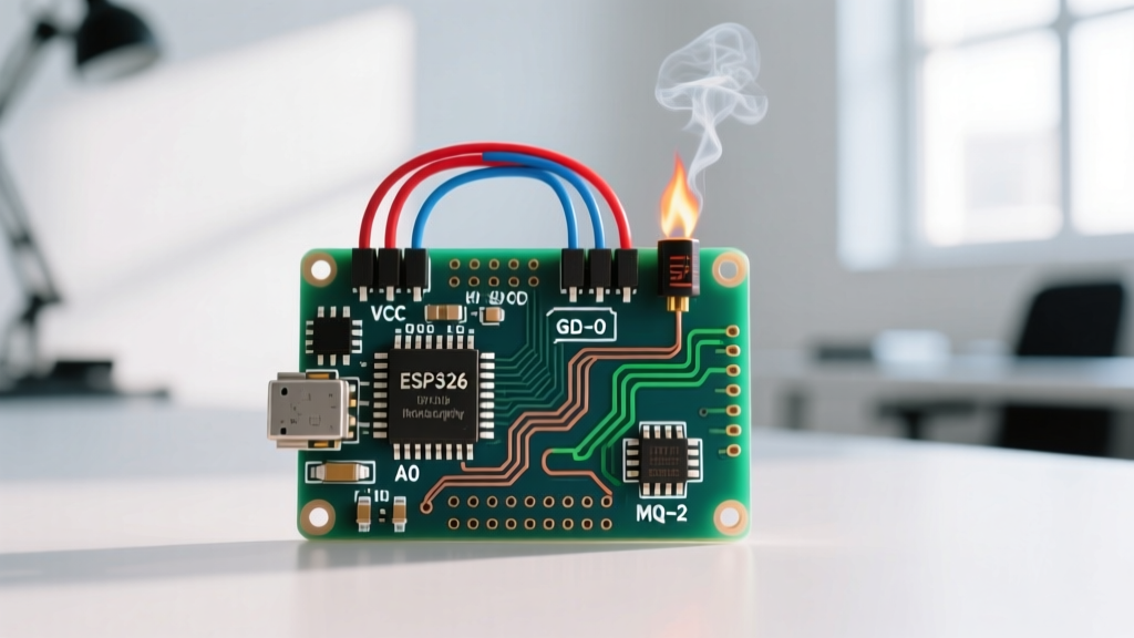
- MQ-2 Analog Out (AOUT): Connect to Arduino A0. Place a 100nF ceramic capacitor between A0 and GND to filter high-frequency switching noise.
- KY-026 Analog Out (A0): Connect to Arduino A1.
- KY-026 Digital Out (D0): Connect to Arduino D2 (configured with internal pull-up for hardware interrupt capability).
- Relay IN: Connect to Arduino D8 via a 220Ω current-limiting resistor.
- Buzzer VCC: Connect to Arduino D9 (use PWM for variable tone generation if desired).
Deep Dive: MQ-2 Burn-In and Rs/R0 Calibration
The most common failure mode in DIY Arduino fire detectors is skipping the MQ-2 stabilization phase. The SnO2 sensing layer requires a continuous 24 to 48-hour "burn-in" period to oxidize surface contaminants and stabilize its baseline conductivity. If you calibrate the sensor immediately after unboxing, your baseline readings will drift downward over the first week, rendering your hardcoded thresholds useless.
Calculating the Clean Air Ratio
According to the Hanwei datasheet, the MQ-2 has a standard circuit configuration where the surface resistance (Rs) and clean air resistance (R0) yield a ratio of approximately 9.8. The standard breakout board includes a 1KΩ load resistor (RL). To find the actual Rs in your environment, use the voltage divider formula:
Rs = ( (Vc / Vout) - 1 ) * RL
Where Vc is your supply voltage (5.0V) and Vout is the voltage read at the analog pin. For a deeper understanding of how the microcontroller samples this voltage, refer to the Arduino analogRead() documentation, which details the 14-bit ADC resolution on the Uno R4 compared to the legacy 10-bit ADC.
Engineering Warning: Never expose the MQ-2 to silicone vapors during the burn-in phase or deployment. Silicone off-gassing (common from bathroom sealants and certain 3D printing adhesives) permanently poisons the SnO2 catalytic surface, destroying its sensitivity to combustible gases.
Tuning the KY-026 Flame Sensor for IR Rejection
The KY-026 module utilizes a bare IR photodiode paired with an LM393 comparator. It detects electromagnetic radiation between 760nm and 1100nm. However, ambient IR sources—such as direct sunlight, halogen bulbs, and incandescent heaters—occupy this exact spectrum.
To configure the sensor for your specific deployment environment, you must tune the onboard blue trimpot (potentiometer):
- Step 1: Power the module and connect a multimeter to the digital output (D0) pin.
- Step 2: Expose the sensor to the worst-case ambient lighting in the deployment room (e.g., direct afternoon sunlight through a window).
- Step 3: Slowly turn the trimpot clockwise until the D0 pin output transitions from LOW (0V) to HIGH (5V).
- Step 4: Back the trimpot off by exactly one-eighth of a turn counter-clockwise. This establishes a safety margin, ensuring ambient IR registers as LOW, while a localized flame (which outputs intense, concentrated 940nm IR) triggers a HIGH state.
Implementing Hysteresis in the Firmware Logic
A naive firmware approach uses a single threshold (e.g., if (smoke_level > 400) trigger_alarm()). In a real fire scenario, smoke density fluctuates due to HVAC drafts and thermal convection currents. This fluctuation causes the sensor value to rapidly cross the threshold back and forth, resulting in "relay chatter." This oscillation will physically destroy mechanical relays and cause severe audio fatigue from a stuttering buzzer.
To resolve this, implement hysteresis (a dual-threshold state machine):
- Trigger Threshold (Upper Bound): 450 ADC units. When the moving average exceeds this, the system enters the
ALARMstate and latches the relay HIGH. - Reset Threshold (Lower Bound): 320 ADC units. The system will only exit the
ALARMstate and release the relay when the smoke level drops below this significantly lower value, requiring manual ventilation or fire suppression. - Sampling Rate: Implement a 16-sample moving average filter executing every 500ms. This filters out transient electrical noise without delaying critical fire detection.
Environmental Failure Modes & Edge Cases
Even perfectly calibrated sensors fail when environmental physics are ignored. When deploying your Arduino fire detector, account for these documented edge cases:
- Humidity Spikes: The MQ-2 is cross-sensitive to high relative humidity. If deployed in a damp basement or near a kitchen boiling pot, water vapor can adsorb onto the SnO2 layer, artificially lowering resistance and mimicking a smoke event. Pair the MQ-2 with an SHT40 temp/humidity sensor in software to apply a humidity compensation offset.
- Dust Accumulation: Over 12-18 months, airborne particulate matter will coat the stainless steel mesh of the MQ-2 and the epoxy lens of the KY-026. This attenuates IR transmission and restricts gas flow, increasing response latency.
- Thermal Stratification: Smoke rises. Mounting the detector at standard electrical outlet height (12 inches from the floor) is useless for smoke detection. Following the NFPA 72 National Fire Alarm and Signaling Code, smoke sensors must be mounted on the ceiling or high on the wall (within 12 inches of the ceiling line) to intercept the thermal plume.
Compliance and Safety Disclaimer
While building an Arduino fire detector is an excellent exercise in sensor fusion, embedded C++, and hardware calibration, it must never replace certified life-safety equipment. The NIST Fire Research Division conducts rigorous testing on smoke alarm reliability, demonstrating that consumer-grade chemiresistive sensors lack the long-term stability and UL-certified fail-safes required for primary life safety. Use your Arduino configuration as a supplementary IoT alert system (e.g., sending MQTT push notifications to your phone when you are off-site), but always maintain code-compliant, hardwired or battery-backed UL-listed smoke and carbon monoxide detectors in your living spaces.