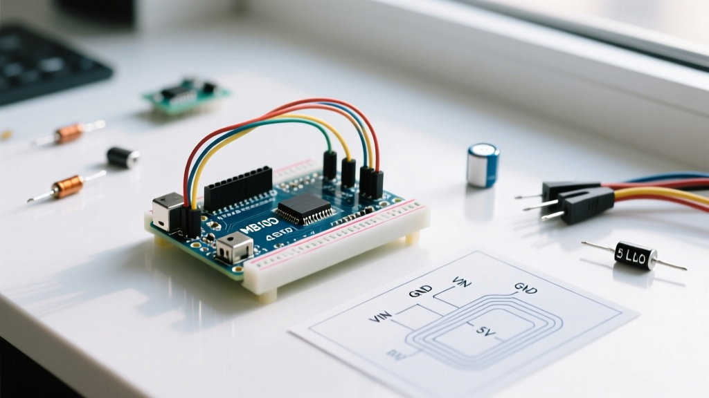

The Reality of RGB LED and Arduino Integration
Integrating a standard 4-pin RGB LED and Arduino microcontroller seems like a trivial weekend project, yet it remains one of the most frequent sources of frustration in maker forums. Whether you are using a classic ATmega328P-based board or the newer Renesas RA4M1-powered Arduino Uno R4 Minima (retailing around $27.50 in 2026), the fundamental physics of light-emitting diodes do not change. Mismatched forward voltages, incorrect PWM pin assignments, and common-anode logic inversion routinely result in flickering outputs, washed-out colors, or completely dead channels.
This comprehensive troubleshooting guide bypasses basic blink tutorials and dives straight into the electrical engineering realities of discrete RGB LEDs. We will cover exact resistor calculations, multimeter diagnostic flows, and software-level PWM fixes to ensure your color mixing is flawless.
Rapid Diagnostic Matrix: Symptoms and Solutions
Before ripping apart your breadboard, match your specific symptom to the diagnostic matrix below. This table addresses the most common failure modes when pairing an RGB LED and Arduino.
| Symptom | Probable Root Cause | Hardware / Software Fix |
|---|---|---|
| Colors are inverted (e.g., code says Red, LED shows Cyan) | Using Common Anode LED with Common Cathode code logic | Invert PWM values in code: analogWrite(pin, 255 - value) |
| Red channel overpowers Green and Blue (muddy orange/yellow) | Single current-limiting resistor used on the common pin | Remove common resistor; add individual resistors to R, G, and B pins |
| Flickering or ghosting during color transitions | PWM frequency interference or breadboard parasitic capacitance | Move to hardware Timer1 PWM; add 100nF decoupling capacitors |
| Only one color works, others remain dead | Blown internal bond wire or incorrect pinout assumption | Test with multimeter diode mode; verify datasheet pinout |
| LED gets physically hot to the touch | Exceeding 20mA continuous forward current per die | Increase resistor values; check for shorted GPIO pins |
Pinout Identification: The Multimeter Method
Never trust the physical leg length of an RGB LED. While the longest leg is typically the common pin (anode or cathode), manufacturing variances—especially with budget components from overseas marketplaces—frequently result in non-standard pinouts. According to the SparkFun LED Tutorial, relying on visual inspection is a primary cause of dead channels.
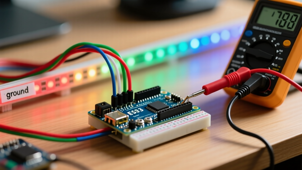
To definitively identify the pins of your RGB LED and Arduino setup, use a digital multimeter (DMM) in Diode Test Mode:
- Set your DMM to the diode symbol.
- Place the black probe on the longest leg (suspected common pin).
- Touch the red probe to each of the remaining three legs.
- Note the forward voltage drop displayed on the DMM. You should see approximately 1.8V - 2.2V for Red, and 3.0V - 3.4V for Green and Blue.
- If the DMM reads 'OL' (Open Loop) or infinite resistance, swap the probes. If it conducts with the red probe on the long leg, you have a Common Anode LED. If it conducts with the black probe on the long leg, it is Common Cathode.
The Fatal Flaw: Single Resistor vs. Individual Resistors
The most pervasive electrical error in beginner RGB LED and Arduino projects is placing a single current-limiting resistor on the common pin. This violates basic circuit theory and results in severe color shifting.
Understanding Current Hogging
An RGB LED contains three distinct semiconductor dies in one package. Each die has a different forward voltage ($V_f$). For a standard Kingbright WP154A4SUREQBFZW 5mm diffused RGB LED, the typical forward voltages at 20mA are:
- Red: 2.0V
- Green: 3.2V
- Blue: 3.2V
If you connect a single resistor to the common cathode and attempt to mix Red and Green simultaneously, the current will follow the path of least resistance. The Red die (2.0V drop) will 'hog' the current, clamping the voltage across the parallel circuit. Because the Green die requires 3.2V to turn on, it will remain completely dark or extremely dim, leaving you with a purely red output regardless of your code.
Calculating Exact Resistor Values
You must use three separate resistors, one for each color channel. Using Ohm's Law ($R = (V_{source} - V_f) / I_f$) for a 5V Arduino Uno R3 (referencing the Arduino Uno R3 Documentation for exact 5V rail tolerances):
- Red Resistor: $(5V - 2.0V) / 0.02A = 150\Omega$
- Green Resistor: $(5V - 3.2V) / 0.02A = 90\Omega$ (Use standard $100\Omega$)
- Blue Resistor: $(5V - 3.2V) / 0.02A = 90\Omega$ (Use standard $100\Omega$)
Pro-Tip for 3.3V MCUs: If you are using an Arduino Nano 33 IoT or ESP32 (3.3V logic), the Red channel will work fine ($R = 65\Omega$), but Green and Blue will be incredibly dim because $3.3V - 3.2V = 0.1V$, leaving almost no voltage headroom for the resistor. You must use a logic-level MOSFET or a dedicated LED driver IC for 3.3V systems driving standard 3.2V RGB dies.
Software Inversion and PWM Ghosting
Hardware wiring is only half the battle. The software implementation of the analogWrite() function, detailed in the Arduino analogWrite() Reference, behaves differently depending on your LED type.
Common Anode Logic Inversion
In a Common Cathode LED, 0V is OFF and 5V (PWM 255) is ON. In a Common Anode LED, the common pin is tied to 5V. Therefore, pulling the GPIO pin to 0V (PWM 0) creates the maximum voltage differential, turning the LED fully ON. Pulling the pin to 5V (PWM 255) results in 0V differential, turning it OFF.
To fix inverted colors without rewiring, apply this mathematical inversion in your sketch:
analogWrite(redPin, 255 - desiredRedValue);
Eliminating PWM Flicker and Ghosting
Standard Arduino PWM operates at roughly 490Hz (or 980Hz on pins 5 and 6). When driving long wires or high-capacitance breadboards, this frequency can cause visible flickering or 'ghosting' (where a channel faintly glows even when set to 0). To resolve this:
- Add Pull-down/Pull-up Resistors: Place a $10k\Omega$ resistor between each PWM pin and Ground (for Common Cathode) to ensure the pin is firmly pulled low when the MCU is booting or in high-impedance states.
- Use Hardware Timers: Utilize the
TimerOnelibrary to increase the PWM frequency to 20kHz, pushing the flicker completely out of the human visual spectrum and eliminating parasitic capacitance charging delays.
Scaling Up: High-Power RGB LEDs and MOSFETs
Standard 5mm RGB LEDs are limited to 20mA per channel. If your project requires high-power RGB star LEDs (e.g., 3W or 5W modules drawing 350mA to 700mA), you cannot wire them directly to the Arduino. The ATmega328P has an absolute maximum DC current limit of 40mA per I/O pin, and a total package limit of 200mA. Exceeding this will permanently destroy the microcontroller's silicon.
Instead, use N-channel logic-level MOSFETs like the IRLB8721 or IRLZ44N. These components can be driven directly by the Arduino's 5V PWM pins and can safely switch up to 30A of continuous current. Wire the Arduino PWM pin to the MOSFET Gate (via a $100\Omega$ gate resistor to prevent ringing), the LED cathode to the Drain, and the Source to Ground. Remember to mount the MOSFET on a heatsink if drawing more than 1A.
Step-by-Step Multimeter Troubleshooting Flow
When your RGB LED and Arduino circuit refuses to cooperate, follow this strict isolation sequence to identify the exact point of failure:
- Step 1: Isolate the MCU. Disconnect the LED entirely. Upload a basic blink sketch to the PWM pins. Use your DMM in DC Voltage mode to verify the pins are toggling between 0V and 5V (or 3.3V).
- Step 2: Test the Breadboard. Breadboard contact resistance can degrade over time, causing voltage drops. Measure the voltage directly at the LED legs while the circuit is powered. If it reads significantly lower than the MCU pin, replace the breadboard or use soldered perfboard.
- Step 3: Verify Resistor Integrity. Remove power. Set the DMM to Ohms. Probe both sides of your current-limiting resistors. Ensure they haven't been damaged by heat or shorted by stray wire clippings.
- Step 4: Check for Thermal Throttling. If the LED works for 10 seconds and then dims or shifts color, touch the epoxy lens. If it is hot, your internal thermal management is failing. Reduce the PWM duty cycle to 50% or add an external heatsink to the LED leads.
By treating your RGB LED and Arduino integration as a precise electrical system rather than a simple plug-and-play toy, you eliminate the guesswork. Proper resistor sizing, pinout verification, and PWM management will guarantee smooth, vibrant color mixing for any embedded project.