
The MCP2515 Arduino Ecosystem: Why Initialization Fails
Integrating Controller Area Network (CAN) bus communication into Arduino projects is a rite of passage for automotive and industrial makers. The Microchip MCP2515 standalone CAN controller, paired with a TJA1050 transceiver, remains the most cost-effective gateway to the CAN bus in 2026. Generic clone modules from brands like HiLetgo or MakerHawk typically cost between $3 and $6, compared to $25+ for official Seeed Studio CAN-BUS shields.
However, the MCP2515 is notorious for throwing initialization errors, leaving makers staring at a serial monitor that endlessly prints CAN Init Fail. Because the MCP2515 relies on a multi-layer architecture—SPI communication between the microcontroller and the CAN controller, followed by analog differential signaling from the transceiver to the bus—errors can originate in the code, the logic wiring, or the physical layer. This guide provides a deep-dive diagnostic framework to isolate and resolve MCP2515 Arduino errors systematically.
Error 1: The Crystal Oscillator Mismatch (CAN_INITFAIL)
The single most common cause of CAN.begin() failure in the popular mcp_can library (maintained by Cory Fowler) is a clock frequency mismatch. The MCP2515 does not generate its own baud rate; it calculates the time quanta based on the external crystal oscillator connected to its OSC1 and OSC2 pins.
The Clone Board Dilemma
Many cheap MCP2515 modules feature a silkscreen label claiming an 8MHz crystal, but the factory actually soldered a 16MHz crystal to cut BOM costs (or vice versa). If your Arduino code initializes the library with an 8MHz clock definition, but the hardware is running at 16MHz, the internal baud rate generator will calculate timings at exactly half the intended speed. The node will fail to synchronize with the bus, triggering bit errors and dropping offline.
- Diagnostic Step: Physically inspect the metal can of the crystal oscillator on your module. It will be stamped with either '8.000' or '16.000'.
- Code Fix: In your setup function, ensure the third parameter of the initialization call matches the hardware. For a 16MHz crystal at 500kbps, use:
CAN.begin(MCP_ANY, CAN_500KBPS, MCP_16MHZ). For an 8MHz crystal, useMCP_8MHZ.
Error 2: SPI Communication & Logic Level Faults
If the crystal is correct but the Arduino still cannot configure the MCP2515, the SPI bus is failing. The MCP2515 operates at 3.3V logic internally, though many modules include a 3.3V LDO regulator and claim 5V tolerance on the SPI pins. Pushing 5V logic from an Arduino Uno directly into the SI, SO, and SCK pins of a marginal clone board can degrade the silicon over time or cause immediate latch-up.
SPI Pinout and Voltage Verification
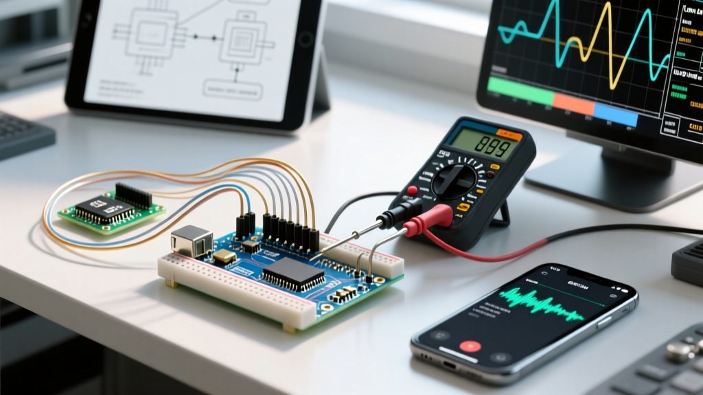
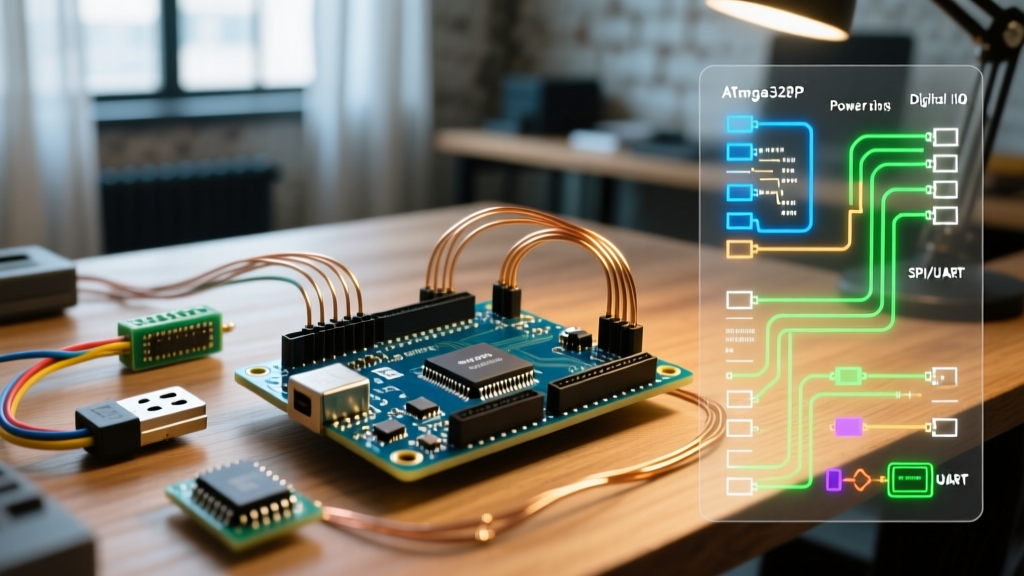
Use a digital multimeter (DMM) to verify the SPI connections. The standard Arduino SPI documentation dictates the hardware SPI pins, but the Chip Select (CS) pin is user-definable and frequently misconfigured in code.
| Signal | Arduino Uno/Nano Pin | MCP2515 Module Pin | Expected Idle Voltage (5V Arduino) |
|---|---|---|---|
| VCC | 5V | VCC | 4.9V - 5.1V |
| GND | GND | GND | 0V |
| CS (SS) | D9 or D10 | CS | 3.3V (Pulled High) |
| SCK | D13 | SCK | 0V (Idle Low) |
| SI (MOSI) | D11 | SI | 0V (Idle Low) |
| SO (MISO) | D12 | SO | 0V or 3.3V (Floating/Driven) |
| INT | D2 | INT | 3.3V (Pulled High) |
Pro-Tip: If you are using an ESP32 or a 3.3V Arduino Zero, you must wire the VCC pin to the board's 3.3V output. Feeding 5V into the VCC pin of an MCP2515 module when using a 3.3V microcontroller will destroy the ESP32's SPI pins via the MISO return line.
The 'CANCTRL' Register Bypass Test
When the mcp_can library fails silently or hangs, bypass the abstraction layer. Write a raw SPI script to read the MCP2515's CANCTRL register (Address 0x0F). Upon a successful hardware reset, this register must return 0x87. If your raw SPI read returns 0x00 or 0xFF, the SPI wiring is broken, the CS pin is incorrect, or the MCP2515 silicon is dead. This raw register check isolates hardware SPI faults from library-level CAN configuration bugs.
Error 3: TJA1050 Transceiver & Physical Layer Failures
Once the Arduino successfully initializes the MCP2515 (returning CAN_OK), you may find that no messages are actually transmitted or received. The error has now shifted from the digital SPI domain to the analog physical layer, specifically the TJA1050 CAN transceiver.
The 5V Transceiver Trap
The TJA1050 transceiver requires a strict VCC supply of 4.75V to 5.25V to drive the differential CANH and CANL signals. A common mistake in 2026 maker projects is attempting to power the entire MCP2515 module from a 3.3V rail to match a Raspberry Pi Pico or ESP32. While the MCP2515 chip will operate fine at 3.3V, the TJA1050 will remain in a high-impedance offline state. It will not drive the bus, resulting in CAN_FAILTX errors when the MCP2515 attempts to send a frame and fails to detect the dominant bit echo.
Multimeter Diagnostics for the Physical Layer
According to the ISO 11898-2 standard, heavily referenced by CAN in Automation (CiA), the physical layer relies on specific differential voltages. Connect your DMM's black probe to the module's GND and the red probe to CANH and CANL while the bus is idle (recessive state).
- CANH to GND (Idle): Should read ~2.5V.
- CANL to GND (Idle): Should read ~2.5V.
- CANH to CANL (Idle): Should read ~0.0V (Differential voltage is zero).
If you read 0V on both CANH and CANL relative to ground, the TJA1050 is unpowered or dead. If you read 5V on CANH and 0V on CANL, the transceiver is stuck in a dominant state, usually caused by a short circuit on the bus or a blown transceiver IC.
Error 4: Missing or Incorrect Bus Termination
CAN bus requires a 120-ohm termination resistor at both physical ends of the network to prevent signal reflection. Most generic MCP2515 modules include a 'J1' jumper or a small 1206 SMD resistor near the TJA1050 chip to provide this termination.
Diagnosing Reflection Errors
If your Arduino node works perfectly when sitting next to the ECU on a 1-meter cable, but throws CAN_ERROR or bit-stuffing faults when you extend the cable to 5 meters, you have a termination or signal integrity issue.
- Disconnect all power from the CAN network.
- Set your multimeter to resistance (Ohms) mode.
- Measure the resistance between CANH and CANL at any node on the bus.
- Expected Reading: ~60 ohms (indicating two 120-ohm resistors in parallel at the ends of the bus).
- Troubleshooting: If you read 120 ohms, you are missing a terminator on the far end. If you read 40 ohms or less, you have too many terminators (multiple modules with their J1 jumpers closed). Open the J1 jumper on all nodes except the two physically furthest apart.
Advanced Diagnostic Matrix
Use this matrix to quickly cross-reference your serial monitor output with physical symptoms to pinpoint the exact failure domain.
| Serial Output / Symptom | Probable Domain | Root Cause & Action |
|---|---|---|
CAN Init Fail | SPI / Code | Wrong crystal defined in CAN.begin(), or CS pin mismatch. |
CAN Init OK, but no TX/RX | Physical / Power | TJA1050 powered by 3.3V instead of 5V. Check VCC rail. |
CAN_FAILTX on send | Physical / Bus | Missing 120-ohm termination, or no other active node to ACK. |
Reads 0xFF on SPI register dump | SPI Wiring | MISO/SO wire broken, or SPI clock speed too high (>10MHz). |
| Bus works for 5 mins, then crashes | Thermal / Noise | TJA1050 overheating due to bus short, or missing common ground. |
Final Thoughts on Grounding and Isolation
A frequently overlooked requirement in automotive CAN bus diagnostics is the common ground. The TJA1050 transceiver can tolerate a maximum ground offset of about 2V between nodes. If you are testing an MCP2515 Arduino setup against a running vehicle's OBD2 port using a bench power supply, ensure the Arduino's GND is tied to the vehicle's chassis ground. Without a shared reference ground, the differential voltage will exceed the transceiver's common-mode range (-2V to +7V), resulting in total communication blackout and potential hardware damage. Always verify your ground continuity before applying power to the CAN bus.