
The Evolution of Arduino Pinouts in 2026
As of 2026, the maker ecosystem has firmly transitioned toward 32-bit ARM Cortex-M and RISC-V architectures, with boards like the Arduino Uno R4 and Nano ESP32 dominating workbenches. However, understanding the exact electrical characteristics of the pins for Arduino boards remains a critical point of failure. Whether you are migrating from the legacy 8-bit ATmega328P or designing a custom shield, misinterpreting pin tolerances, logic levels, and current limits will result in fried silicon and erratic sensor readings.
This quick reference guide and FAQ cuts through the fluff, providing actionable, datasheet-backed specifications and real-world wiring frameworks to protect your hardware and optimize your sketches.
Quick Reference: Arduino Pin Specifications Matrix
Before diving into specific wiring scenarios, review the hardware-level differences between the most popular development boards used today. Note that pricing reflects average 2026 market rates for genuine boards.
| Specification | Uno R3 (ATmega328P) | Uno R4 Minima (RA4M1) | Nano ESP32 (ESP32-S3) |
|---|---|---|---|
| Core Architecture | 8-bit AVR | 32-bit ARM Cortex-M4 | 32-bit Dual-Core Xtensa |
| Operating Voltage | 5V | 5V (Logic is 5V tolerant) | 3.3V |
| Recommended I/O Current | 20 mA per pin | 8 mA per pin | 40 mA absolute max |
| ADC Resolution | 10-bit (1024 steps) | 14-bit (16384 steps) | 12-bit (4096 steps) |
| DAC Output | None (PWM only) | 8-bit True DAC | None (PWM only) |
| Approx. Genuine Price | $27.00 | $20.00 | $19.50 |
Frequently Asked Questions (FAQ) About Pins for Arduino
1. What is the maximum current draw for Arduino digital pins?
This is the most common way beginners destroy microcontrollers. The absolute maximum current rating is not a target; it is the threshold before thermal damage occurs.
- Uno R3 (ATmega328P): The recommended continuous current is 20 mA per pin, with an absolute maximum of 40 mA. However, the total current across all VCC and GND pins combined must not exceed 200 mA. If you power ten LEDs at 20 mA each, you will brownout the MCU.
- Uno R4 (Renesas RA4M1): The RA4M1 has stricter per-port group limits. While a single pin can handle up to 8 mA safely, the total current for a specific port group (e.g., Port A or Port 1) is often capped at 15 mA to 30 mA total. Drawing 8 mA from P101 and another 8 mA from P102 may exceed the port group limit, causing voltage sag or permanent silicon degradation.
- Nano ESP32: While individual GPIO pins can source up to 40 mA, the total package limit for all GPIOs combined is roughly 1100 mA. Furthermore, pins used for strapping (boot configuration) have weak internal pull-downs that can cause boot failures if heavy loads are attached during startup.
Expert Rule of Thumb: Never source more than 50% of the recommended pin current for continuous operation. For any load exceeding 15 mA, use a logic-level N-channel MOSFET (like the IRLZ44N) or a dedicated LED driver IC (like the TLC5940).
2. Can I use Arduino PWM pins to drive a DC motor directly?
No. Under no circumstances should you connect a DC motor, solenoid, or relay coil directly to any PWM or digital pins for Arduino boards. Motors are highly inductive loads. When the PWM signal switches off, the collapsing magnetic field generates a massive reverse voltage spike (back-EMF) that can easily exceed 50V, instantly punching through the microcontroller's internal GPIO protection diodes and frying the chip.
The Correct Wiring Framework:
- Use a motor driver IC like the DRV8833 (for low voltage, up to 10.8V) or an L298N (for higher voltage, though inefficient due to bipolar transistor voltage drops).
- If building a custom single-direction driver, use a logic-level MOSFET and place a Schottky flyback diode (e.g., 1N5819) in reverse parallel across the motor terminals to safely route the back-EMF spike back into the power rail.
- Always use a separate power supply for the motor, tying only the grounds together with the Arduino.
3. How do analog pins for Arduino differ between the R3 and R4?
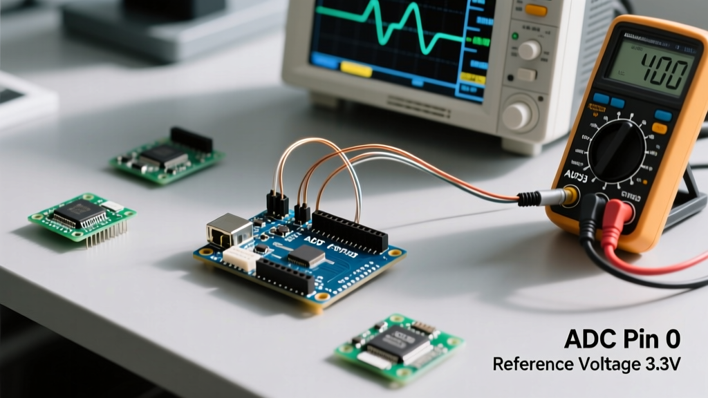
The transition from 8-bit to 32-bit architectures brought massive improvements to Analog-to-Digital Converter (ADC) resolution, but it requires code adjustments.
The classic Uno R3 features a 10-bit ADC, mapping 0-5V to integer values between 0 and 1023. The Uno R4 features a 14-bit ADC, mapping 0-5V to 0-16383. However, by default, the Arduino IDE scales the R4's 14-bit reading down to 10-bit for backward compatibility with legacy sketches. To unlock the full precision for high-resolution sensor arrays (like precise thermistor thermometry or strain gauges), you must explicitly declare analogReadResolution(14); in your setup() block.
Note on the ESP32: The Nano ESP32 features a 12-bit ADC, but it is notoriously non-linear at the voltage extremes. Readings below 0.15V and above 3.1V will saturate and return inaccurate flat values. For precision analog work on ESP32 boards, route the signal through an external ADC like the ADS1115 via I2C.
4. What happens if I feed 5V into a 3.3V Arduino pin?
If you are using a 3.3V board (like the Nano ESP32, Zero, or Due) and connect a 5V sensor output directly to a GPIO pin, you will forward-bias the internal ESD protection diodes. This will cause excessive current to flow into the VCC rail, potentially resetting the board, corrupting flash memory, or permanently latching the pin in a short-circuit state.
Solutions for Logic Level Translation:
- Voltage Divider: For low-speed unidirectional signals (like an ultrasonic sensor Echo pin), use a resistor divider (e.g., 2kΩ to GND, 3.3kΩ in series with the signal). This drops 5V down to a safe ~3.1V.
- Dedicated Level Shifter: For bidirectional buses like I2C or high-speed SPI, use a Texas Instruments TXS0108E or a BSS138 MOSFET-based bi-directional logic level converter module. These typically cost under $2.00 in 2026 and prevent data corruption caused by RC delay in resistor dividers.
Advanced Pin Configurations & Edge Cases
Interrupt Mapping: Legacy vs. Modern NVIC
On the legacy Uno R3, hardware external interrupts were strictly limited to Digital Pin 2 (INT0) and Digital Pin 3 (INT1). If you needed more, you had to use Pin Change Interrupts (PCINT), which required complex register manipulation and triggered on any state change within a port group.
Modern 32-bit boards like the Uno R4 utilize an ARM Nested Vectored Interrupt Controller (NVIC). This means almost every digital pin can be assigned as a dedicated hardware interrupt using the standard attachInterrupt(digitalPinToInterrupt(pin), ISR, MODE) function. This drastically simplifies rotary encoder decoding and high-speed pulse counting.
I2C Bus Capacitance and Pull-Up Resistors
When wiring multiple I2C sensors to the dedicated SDA/SCL pins, the bus capacitance increases with every wire and module added. The internal pull-up resistors on Arduino pins (typically 20kΩ to 50kΩ) are far too weak to pull the line high quickly enough at standard I2C speeds, resulting in corrupted data and Wire.endTransmission() timeouts.
According to Analog Devices I2C design primers, the maximum allowable bus capacitance is 400 pF. If your wiring exceeds this, or if you are running at 400 kHz (Fast Mode), you must disable internal pull-ups and install external 4.7kΩ (for 100 kHz) or 2.2kΩ (for 400 kHz) resistors tied directly to the VCC rail. For a deep dive into official pin behaviors, refer to the Arduino Digital Pins Guide.
Essential Wiring Rules to Prevent Board Damage
To ensure longevity of your microcontroller and stable sensor readings, adhere to these non-negotiable hardware practices:
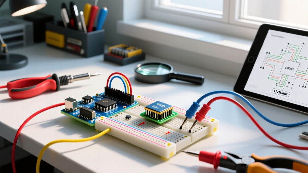
- Common Ground: When using external power supplies for motors, relays, or high-power LEDs, the GND of the external supply must be tied to the Arduino GND. Without a common ground reference, the logic signals will float, causing erratic behavior and potential over-voltage on the GPIO pins.
- Decoupling Capacitors: Always place a 100nF (0.1µF) ceramic capacitor across the VCC and GND rails of any external sensor or IC, positioned as physically close to the chip as possible. This filters out high-frequency switching noise that the Arduino's onboard regulator cannot handle.
- Hot-Swapping Sensors: Never connect or disconnect I2C or SPI sensors while the Arduino is powered on unless the module specifically supports hot-swap. Plugging in a module with reversed VCC/GND pins, even for a millisecond, will backfeed current through the data pins and destroy the MCU's I/O matrix.
Final Thoughts on Hardware Selection
Understanding the physical and electrical realities of the pins for Arduino boards bridges the gap between a sketch that compiles and a product that survives in the real world. Whether you are leveraging the 14-bit ADC of the Uno R4 for precision telemetry or managing the strict current budgets of the RA4M1 port groups, always consult the specific Arduino Uno R4 Minima Official Documentation or the relevant silicon datasheet before finalizing your PCB layout or breadboard wiring.