
Understanding the Arduino Serial Interface
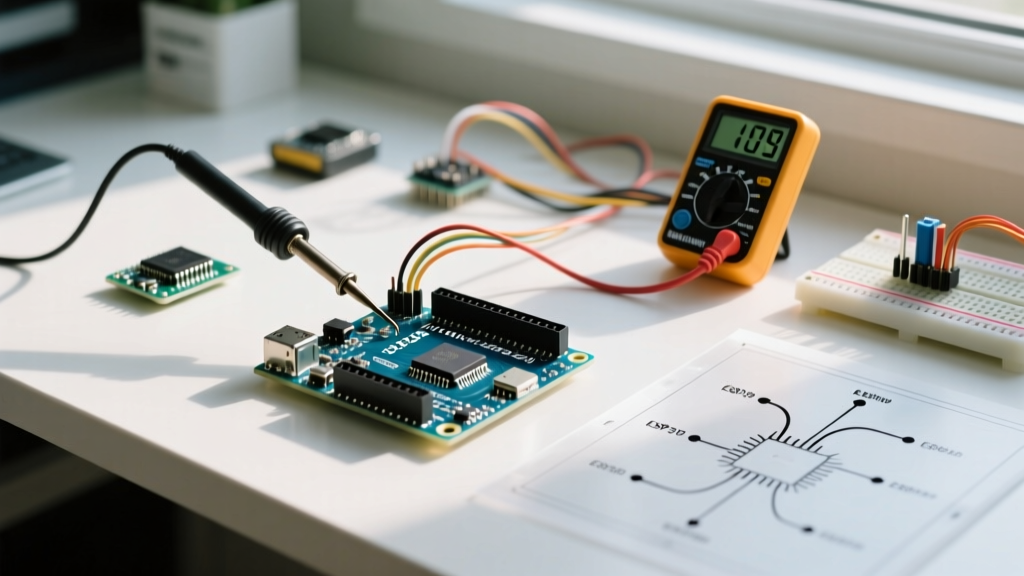
The Arduino serial interface is the backbone of microcontroller debugging, data logging, and inter-device communication. At its core, it relies on UART (Universal Asynchronous Receiver-Transmitter) protocol, a hardware standard that translates data between parallel and serial forms. Whether you are sending sensor telemetry to a Raspberry Pi or simply printing debug strings to the Arduino IDE Serial Monitor, mastering this interface is non-negotiable for embedded systems development.
Unlike synchronous protocols such as SPI or I2C, UART does not use a clock line to synchronize data transfers. Instead, both the transmitting and receiving devices must agree on a specific baud rate (bits per second) beforehand. According to the SparkFun Serial Communication Guide, standard baud rates include 9600, 19200, 38400, 57600, and 115200. While 9600 is the historical default for basic debugging, modern Maker projects frequently utilize 115200 bps to minimize transmission latency and prevent buffer overflows during high-speed data bursts.
Hardware UART vs. SoftwareSerial: Choosing the Right Path
When designing your circuit, you must decide between using the microcontroller's dedicated hardware UART pins or emulating the protocol in software. The ATmega328P (found on the Arduino Uno and Nano) features one hardware UART, while the ATmega2560 (Arduino Mega) boasts four. If your hardware UART is occupied by USB-to-Serial communication, you might be tempted to use the SoftwareSerial library. However, this comes with severe performance trade-offs.
| Feature | Hardware UART (Serial) | SoftwareSerial |
|---|---|---|
| CPU Overhead | Negligible (handled by UART registers) | Extremely High (disables interrupts during TX/RX) |
| Max Reliable Baud | 2,000,000 bps (theoretical) | 115200 bps (often drops bytes above 57600) |
| Simultaneous RX/TX | Yes (Full Duplex) | No (Half Duplex - cannot listen while transmitting) |
| Pin Flexibility | Fixed (e.g., Pins 0 and 1 on Uno) | Any digital pin |
Expert Recommendation: Reserve hardware UART for high-speed, mission-critical data streams (like GPS NMEA sentences or ESC telemetry). Use SoftwareSerial exclusively for low-speed, intermittent configuration tasks, such as sending a few AT commands to a Bluetooth module during setup.
Deep Dive: Buffer Management and Data Loss
One of the most misunderstood aspects of the Arduino serial interface is the receive buffer. On standard AVR-based boards like the Uno R3, the hardware serial receive buffer is strictly limited to 64 bytes. When a byte arrives at the RX pin, the UART hardware triggers an interrupt, moves the byte into this 64-byte ring buffer, and increments the buffer pointer.
If your main loop() is blocked by a delay() function or a long-running sensor read, and more than 64 bytes arrive before you call Serial.read(), the buffer overflows. The 65th byte is silently discarded, leading to corrupted data frames and shifted parsing indices.
How to Prevent Buffer Overflows
- Non-Blocking Code: Eliminate
delay()and usemillis()for timing. This ensures your loop runs thousands of times per second, constantly draining the serial buffer. - Flow Control: For critical applications, implement software flow control. Have the receiver send an 'X' (pause) character when the buffer reaches 50 bytes, and an 'R' (resume) when it drops below 10 bytes.
- Hardware Upgrades: If you consistently battle buffer limits, migrate to an Arduino Due (SAM3X8E) or an ESP32, which feature significantly larger hardware FIFO buffers and faster clock speeds to process interrupts.
The 5V vs 3.3V Logic Trap: Interfacing with Modern Modules
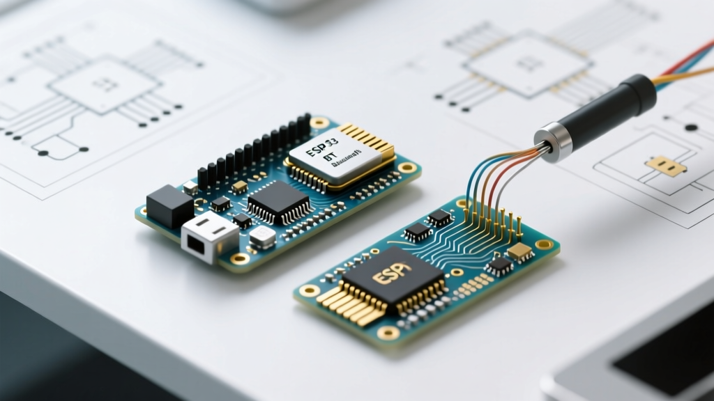
A classic failure mode in modern Maker projects involves connecting a 5V Arduino Uno directly to a 3.3V module, such as an ESP8266 Wi-Fi chip or an XBee radio. The Arduino Uno's TX pin outputs 5V when HIGH. Feeding 5V into the RX pin of a 3.3V microcontroller violates its absolute maximum ratings, potentially degrading the GPIO silicon over time or causing immediate catastrophic failure.
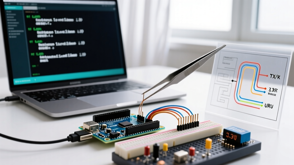
As detailed in the SparkFun Logic Levels Tutorial, you must translate the voltage levels. Here are the two most reliable methods for stepping down the Arduino's 5V TX to a safe 3.3V RX:
Method 1: The Resistor Voltage Divider (Cost: ~$0.10)
For unidirectional signals (Arduino TX to Module RX), a simple resistor divider is highly effective at baud rates up to 115200.
- Connect a 1kΩ resistor in series with the Arduino TX pin.
- Connect a 2kΩ resistor from the junction of the first resistor to Ground (GND).
- Tap the output from the junction and wire it to the 3.3V module's RX pin.
Math Check: Vout = 5V * (2k / (1k + 2k)) = 3.33V. This is perfectly safe for 3.3V logic inputs.
Method 2: Bi-Directional Logic Level Shifters (Cost: ~$2.50)
If you need to send data back from the 3.3V module to the 5V Arduino (Module TX to Arduino RX), the voltage divider won't work reliably, as 3.3V is dangerously close to the ATmega328P's minimum HIGH threshold (typically 0.6 * VCC, or 3.0V). Instead, use a dedicated logic level converter IC like the TXB0108 or a MOSFET-based board featuring the BSS138. These boards safely translate signals in both directions without signal degradation, even at 1 Mbps.
Troubleshooting Matrix: Diagnosing Serial Failures
When the Serial Monitor outputs garbage or remains blank, use this diagnostic matrix to isolate the fault. For more foundational debugging steps, refer to the official Arduino Serial Reference Documentation.
| Symptom | Probable Cause | Actionable Fix |
|---|---|---|
Garbage characters (e.g., ÿÿÿ or squares) |
Baud rate mismatch between transmitter and receiver. | Verify Serial.begin() matches the Serial Monitor dropdown exactly. Check for oscillator timing errors on clone boards. |
| Complete silence (Blank Monitor) | Swapped RX/TX lines or missing common ground. | Cross the wires (TX to RX, RX to TX). Ensure a dedicated GND wire connects both devices. |
| Intermittent data drops or truncated strings | Receive buffer overflow (64-byte limit exceeded). | Remove blocking delays. Increase the frequency of Serial.read() calls in the main loop. |
| Target MCU resets when Serial data is sent | 5V logic overvoltage damaging the 3.3V input protection diodes. | Immediately disconnect. Install a BSS138 logic level shifter on the TX line. |
| Upload fails with 'Programmer not responding' | External hardware attached to Pins 0 and 1 (Hardware UART). | Disconnect all wires from Digital Pins 0 (RX) and 1 (TX) before uploading sketches via USB. |
Pro-Tip for Clone Boards: If you are using a budget Arduino Uno clone featuring the CH340G USB-to-Serial chip instead of the ATmega16U2, you may experience slight timing deviations at ultra-high baud rates (like 250000 or 500000). If you see corrupted data on a clone board, drop your baud rate to 115200 or 57600 to widen the receiver's sampling tolerance window.
Summary
Mastering the Arduino serial interface requires moving beyond basic Serial.println() commands. By understanding the physical limitations of the 64-byte hardware buffer, respecting 3.3V logic thresholds with proper level translation, and systematically diagnosing baud rate and wiring faults, you can build robust, production-ready communication links for your embedded projects.