
The Global Maker's Guide to the Relé Arduino
Whether you are sourcing components in Madrid, Mexico City, or Miami, you have likely encountered the search term relé arduino (Spanish for Arduino relay). While the terminology changes across borders, the underlying physics of electromagnetic switching, optocoupler isolation, and microcontroller logic remain identical. In 2026, the market is flooded with cheap, multi-channel relay modules, but improper wiring remains the leading cause of fried Arduino boards and erratic sketch behavior.
This quick reference guide and FAQ cuts through the fluff, providing exact wiring protocols, power budget calculations, and troubleshooting frameworks for the most ubiquitous relay modules used with Arduino Uno R3, R4, and Nano boards.
Quick Reference Matrix: Common Relay Modules
| Module Type | Common Model | Coil/Logic Voltage | Max Switching Load | Est. Price (2026) | Best Application |
|---|---|---|---|---|---|
| Single Mechanical | SRD-05VDC-SL-C | 5V DC / 5V Trigger | 10A @ 250VAC / 30VDC | $1.50 - $2.20 | Basic lighting, low-draw DC motors |
| Dual Mechanical | SRD-05VDC-SL-C (x2) | 5V DC / 5V Trigger | 10A @ 250VAC / 30VDC | $3.00 - $4.50 | Motor direction control, dual-zone HVAC |
| Solid State (SSR) | Omron G3MB-202P | 5V DC Logic / AC Load | 2A @ 240VAC | $4.50 - $6.00 | PWM AC dimming, high-frequency switching |
| 12V Automotive | SRD-12VDC-SL-C | 12V DC / 5V Logic | 10A @ 250VAC / 30VDC | $2.50 - $3.50 | Car audio, 12V LED strips, winches |
Step-by-Step Wiring: True Optical Isolation
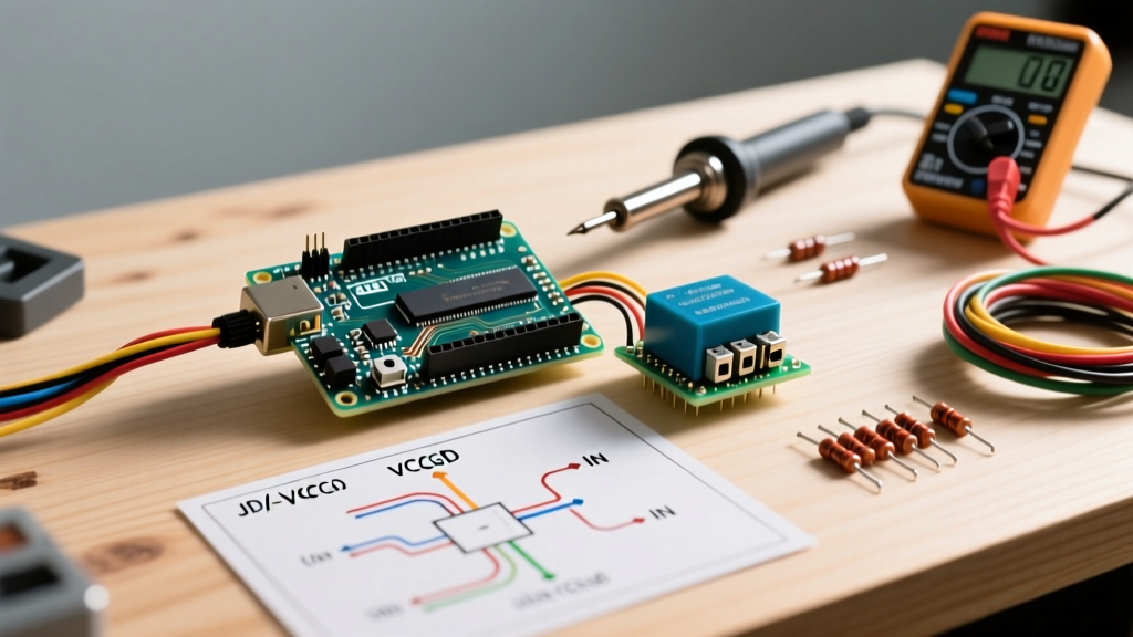
The most critical mistake beginners make with a relé arduino setup is ignoring the JD-VCC jumper on the relay module's PCB. Most 5V relay modules feature an optocoupler (like the PC817) designed to physically separate your microcontroller's logic circuit from the relay's high-current coil circuit. However, factory-default jumper settings defeat this isolation.
How to Wire for Maximum MCU Protection
- Remove the VCC/JD-VCC Jumper: Locate the small plastic jumper bridging the VCC and JD-VCC pins on the relay module. Pull it off.
- Power the Logic Side: Connect the Arduino's
5Vpin to the module'sVCCpin. Connect the Arduino'sGNDto the module'sGND. - Power the Coil Side Independently: Connect an external 5V power supply's positive terminal to
JD-VCCand its negative terminal to the module's dedicatedGND(if available) or share the ground only if the external supply is clean. - Signal Pin: Connect your chosen Arduino digital pin (e.g.,
D8) to the module'sIN1pin.
⚠️ High Voltage Warning: When wiring the NO (Normally Open) or NC (Normally Closed) screw terminals to mains AC (120V/240V), ensure all connections are housed in a UL-listed enclosure. Exposed mains wiring is lethal and violates NEC safety codes.
Baseline Arduino C++ Toggle Code
Most 5V relay modules are active LOW. This means the relay triggers when the signal pin is pulled to GND (0V), and the built-in optocoupler LED illuminates. Always include a startup state in your setup() to prevent the relay from violently chattering or triggering during the Arduino's boot sequence.
const int RELAY_PIN = 8;

void setup() {
  pinMode(RELAY_PIN, OUTPUT);
  // Set HIGH immediately to keep relay OFF (Active LOW module)
  digitalWrite(RELAY_PIN, HIGH);
}

void loop() {
  digitalWrite(RELAY_PIN, LOW);  // Trigger relay (ON)
  delay(2000);                   // Wait 2 seconds
  digitalWrite(RELAY_PIN, HIGH); // Release relay (OFF)
  delay(2000);
}
Relé Arduino FAQ & Troubleshooting
1. Why does my Arduino freeze or reset when the relay clicks?
This is the most common issue in relé arduino projects. It is caused by Back-EMF (Electromotive Force) or voltage sag. When the relay coil is de-energized, the collapsing magnetic field generates a massive reverse voltage spike. If your module lacks a functioning flyback diode (or if it is wired backward), this spike travels back into the Arduino's 5V rail, triggering the microcontroller's brown-out reset (BOD) or permanently damaging the ATmega328P/Renesas RA4M1 chip.
Fix: Verify the diode on the PCB (usually a 1N4148 or 1N4007). Ensure the diode's cathode (the side with the painted ring) faces the positive voltage side. Alternatively, use the JD-VCC isolation method detailed above.
2. Can I power the relay module directly from the Arduino's 5V pin?
No, not safely for continuous operation. A standard SRD-05VDC relay coil draws approximately 70mA to 90mA when engaged. The optocoupler LED draws another 2mA to 5mA. While an Arduino Uno R3's USB port can theoretically supply up to 500mA, the onboard 5V linear regulator (if powered via the barrel jack) can only safely dissipate heat for about 200mA to 300mA of total draw before overheating and shutting down. If you are running sensors, an LCD, and a relay simultaneously, you will exceed the thermal limits of the onboard regulator. Always use a dedicated buck converter or external 5V supply for the relay coils.
3. Mechanical Relay vs. Solid State Relay (SSR): Which should I use?
When building a relé arduino system for AC loads, choosing between mechanical and solid-state is critical. For comprehensive component datasheets and lifecycle ratings, refer to the Omron Global Relays catalog.
| Feature | Mechanical (SRD-05VDC) | Solid State (G3MB-202P) |
|---|---|---|
| Switching Speed | Slow (~10ms) | Instant (Zero-crossing) |
| Lifespan | ~100,000 cycles | Millions of cycles |
| Noise | Audible click | Silent |
| Heat Generation | Negligible | High (Requires heatsink > 1A) |
| AC/DC Support | Both | AC Only (Triac-based) |
Verdict: Use SSRs for high-frequency PWM dimming of AC lights or silent operation. Use mechanical relays for switching DC loads (like 12V water pumps) or when you need to switch both AC and DC with the same module.
4. My relay clicks, but the connected appliance doesn't turn on. Why?
This usually points to a failure on the high-voltage side of the relé arduino circuit. Check the following:
- Contact Pitting/Welding: If you previously switched a highly inductive load (like a large motor or compressor) without a snubber circuit, the mechanical contacts may have arced and welded together, or pitted so badly they no longer make a connection.
- Wrong Terminal: Ensure you are using the NO (Normally Open) and COM (Common) terminals. If you wired into NC (Normally Closed), the appliance will turn ON when the Arduino is off, and turn OFF when the Arduino triggers the relay.
- Loose Strand Connections: Multi-strand wire trapped under the blue screw terminals can easily fray and lose contact. Use ferrule crimps on all stranded wires entering the relay screw terminals.
Advanced Protection: Snubber Circuits for Inductive Loads
When your relé arduino project involves switching inductive loads—such as AC solenoids, large transformers, or HVAC contactors—the mechanical relay contacts are subjected to severe arcing. This arcing generates electromagnetic interference (EMI) that can couple back into your Arduino's signal lines, causing ghost triggers or serial communication corruption.
To mitigate this, wire an RC snubber network in parallel with the load. A standard snubber consists of a 100Ω carbon composition resistor in series with a 0.1µF X2-rated film capacitor. This combination absorbs the inductive kickback and drastically extends the mechanical lifespan of the SRD-05VDC relay contacts, preventing the pitting and welding failures mentioned in the FAQ above.
Further Learning & Microcontroller Safety
Mastering the relé arduino is a rite of passage for electronics hobbyists transitioning from low-voltage logic to real-world power control. Always prioritize galvanic isolation, respect the current limits of your microcontroller's GPIO pins (max 20mA per pin on the Uno R4, as noted in the official Arduino documentation), and never trust a relay module's factory jumper settings when working with high-voltage AC loads.