
Defining the Lab Arduino Environment in 2026
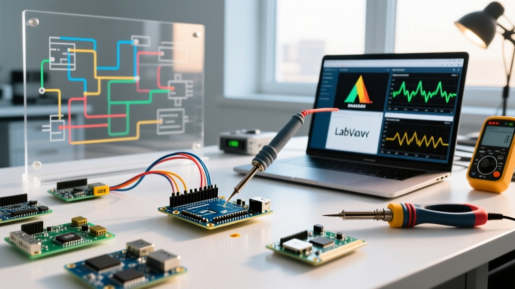
Transitioning an Arduino from a hobbyist workbench to a professional laboratory environment requires a fundamental shift in how we approach hardware compatibility, signal integrity, and software integration. A true lab Arduino setup is not just about blinking LEDs; it involves precise Data Acquisition (DAQ), instrument control, and seamless interoperability with industry-standard software like MATLAB, Simulink, and NI LabVIEW. In 2026, the microcontroller landscape has evolved, offering 32-bit architectures and high-resolution analog-to-digital converters (ADCs) that make Arduino-compatible boards viable for low-to-mid frequency laboratory DAQ tasks, environmental monitoring, and automated test equipment (ATE) triggering.
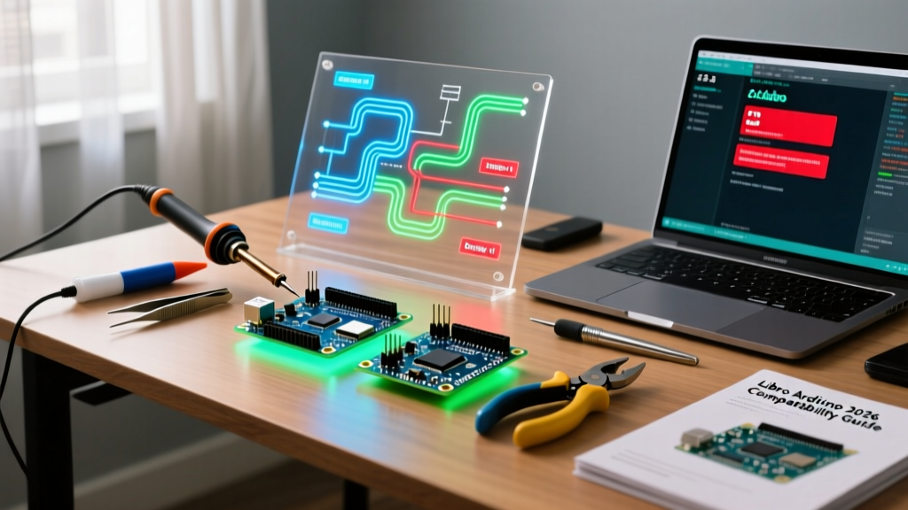
This compatibility guide dissects the exact hardware models, software bridges, and critical failure modes you must navigate to deploy Arduino-based systems in rigorous lab settings.
Hardware Compatibility: Selecting the Right DAQ Board
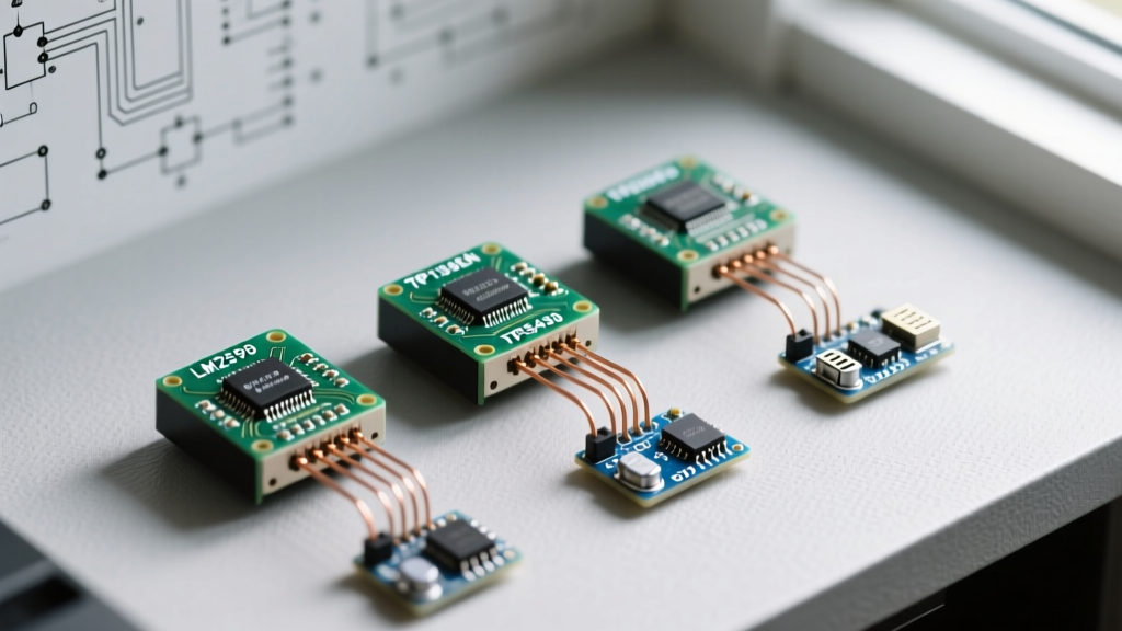
Not all boards bearing the Arduino name are suited for laboratory instrumentation. The classic ATmega328P-based Uno R3, with its 10-bit ADC and 16 MHz clock, is largely obsolete for precision DAQ. Modern lab environments demand higher resolution, faster sampling rates, and 3.3V logic compatibility for interfacing with modern lab sensors and DACs.
| Board Model | Architecture & Clock | ADC Resolution | DAC / PWM | Approx. Price (2026) | Best Lab Use Case |
|---|---|---|---|---|---|
| Arduino Uno R4 Minima | ARM Cortex-M4 (48 MHz) | 14-bit (Hardware) | 12-bit DAC | $22 - $25 | General DAQ, PID control loops, bench power supply monitoring. |
| Arduino Portenta H7 | Dual-Core Cortex-M7/M4 (480/240 MHz) | 16-bit (via external SPI ADC routing) | High-res PWM | $110 - $125 | High-speed DSP, machine vision integration, multi-channel synchronized DAQ. |
| Nano 33 BLE Sense Rev2 | nRF52840 (64 MHz) | 12-bit | Standard PWM | $60 - $65 | Wireless environmental chamber monitoring, vibration analysis (built-in IMU). |
Deep Dive: The Uno R4 Minima ADC Advantage
The Arduino Uno R4 Minima represents a massive leap for lab technicians on a budget. Its Renesas RA4M1 microcontroller features a true 14-bit ADC. When configured correctly in the IDE using analogReadResolution(14), it yields 16,384 discrete steps compared to the 1,024 steps of the legacy R3. This allows for voltage measurements down to ~0.3 mV on a 5V reference scale, making it highly compatible with standard 4-20mA industrial sensor loops when paired with a precision 250-ohm shunt resistor.
Software Integration: Bridging the Gap to Lab Instruments
A microcontroller is only as useful as the software analyzing its data. Interfacing an Arduino with laboratory software requires specific support packages and protocol handlers to prevent serial buffer overflows and latency spikes.
MATLAB & Simulink Compatibility
MathWorks provides the MATLAB Support Package for Arduino Hardware. This package uploads a specialized server sketch to the board, allowing MATLAB to send SCPI-like commands over USB serial.
Lab Tip: When streaming continuous DAQ data to MATLAB, avoid using standard readVoltage in a tight while loop, as the serial handshake introduces a ~15ms latency per read. Instead, utilize the BackgroundScan feature introduced in recent updates, which buffers data on the MCU and transfers it in bulk, achieving near-continuous sampling rates up to 2 kHz on the Uno R4.
NI LabVIEW and LINX
National Instruments (NI) supports Arduino through the LabVIEW MakerHub LINX module. LINX compiles a firmware image that exposes the MCU's I/O as LabVIEW Virtual Instruments (VIs). While excellent for educational labs and slow-moving thermal monitoring, LINX struggles with high-frequency signal capture. For applications requiring >5 kHz sampling in LabVIEW, bypass LINX and write a custom C++ sketch that streams raw binary data via USB CDC, parsing it in LabVIEW using the VISA Read block configured for binary byte arrays.
Python DAQ via Telemetrix
For Python-centric labs, the legacy pyFirmata library is prone to serial bottlenecks. The modern standard is Telemetrix for Arduino. Telemetrix uses an asynchronous callback architecture that prevents the Python GIL (Global Interpreter Lock) from dropping serial packets during heavy computational loads, such as real-time FFT analysis using NumPy and SciPy.
Critical Failure Modes in Lab Environments
Laboratories are electrically noisy, and bench equipment operates on different ground potentials than standard IT equipment. Deploying a lab Arduino without addressing these issues will result in destroyed microcontrollers or corrupted data.
WARNING: The USB Ground Loop Hazard
Connecting an Arduino via USB to a PC while simultaneously connecting its GPIO pins to a benchtop oscilloscope (e.g., Rigol DS1054Z) or function generator creates a ground loop. The USB shield ground and the BNC connector ground will equalize, potentially sending lethal currents through the MCU's ground traces if a fault occurs. Always use a USB isolator (e.g., ADuM4160-based isolators, ~$25) when connecting an Arduino to both a PC and bench instruments.
Signal Integrity and Level Shifting
Most modern lab sensors and high-speed DACs operate at 3.3V logic. The Uno R4 Minima and Portenta H7 are natively 3.3V, but legacy shields and 5V peripherals are still common.
- Directional Level Shifters: Use Texas Instruments TXS0108E for bidirectional I2C/SPI buses. Avoid cheap MOSFET-based shifters for SPI clocks >4 MHz, as the pull-up resistors cause RC delay, corrupting the clock edge.
- Optoisolation: When triggering external high-voltage lab relays or solenoids, use digital isolators like the Texas Instruments ISO7741 rather than standard optocouplers (e.g., PC817) to maintain nanosecond-level propagation delays.
ADC Noise and Power Supply Rejection
Switching power supplies on lab benches introduce high-frequency ripple that destroys ADC precision. The Power Supply Rejection Ratio (PSRR) of the internal voltage reference on budget MCUs is often inadequate. Solution: For precision DAQ, bypass the internal VREF. Feed a clean 4.096V from an external LM4040 precision shunt regulator into the AREF pin, and place a 100nF X7R ceramic capacitor in parallel with a 10uF tantalum capacitor directly at the AREF pin to filter broadband noise.
Step-by-Step: Calibrating the Uno R4 ADC for Precision DAQ
To achieve true 14-bit accuracy, you must calibrate the ADC offset and gain errors. Follow this procedure using a benchtop 6.5-digit multimeter (e.g., Keysight 34461A) as your ground truth.
- Setup: Connect a precision voltage reference (e.g., Fluke 732B or a calibrated lab power supply) to analog pin A0. Connect the multimeter in parallel to measure the exact input voltage.
- Zero-Offset Calibration: Short A0 to AGND. Read the ADC 1,000 times in software, average the results, and store this value as
adc_offset. Subtract this from all future readings. - Gain Calibration: Apply exactly 3.3000V to A0. Read the ADC 1,000 times and average. Calculate the scaling factor:
scale_factor = 3.3000 / (average_reading - adc_offset). - Implementation: In your C++ sketch, apply the formula:
True_Voltage = (raw_adc - adc_offset) * scale_factor. - Validation: Sweep the input voltage from 0.1V to 3.2V in 0.5V steps and log the deviation. A properly calibrated Uno R4 should hold within ±2 mV across the entire range.
Summary Checklist for Lab Deployments
Before deploying any Arduino-based DAQ node into a permanent laboratory rack or test jig, verify the following:
- [ ] Isolation: USB data lines are galvanically isolated from bench instrument grounds.
- [ ] VREF Stability: External precision voltage reference is utilized for ADC measurements requiring <5mV accuracy.
- [ ] Protocol Buffer: Serial communication uses binary packing or asynchronous libraries (Telemetrix) to prevent baud-rate bottlenecks.
- [ ] Watchdog Timer: The hardware watchdog (WDT) is enabled in the sketch to auto-reset the MCU in the event of a stack overflow or I2C bus lockup during unattended weekend testing.
By treating the Arduino not as a toy, but as a configurable embedded DAQ node, laboratories can drastically reduce the cost of automated test equipment while maintaining the rigorous data integrity required for professional engineering and research.