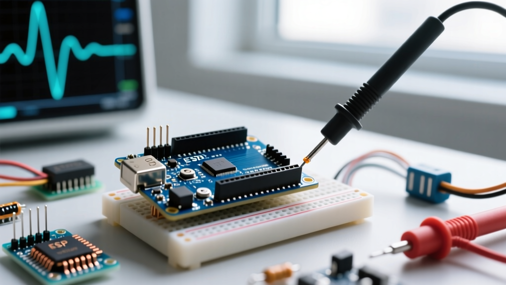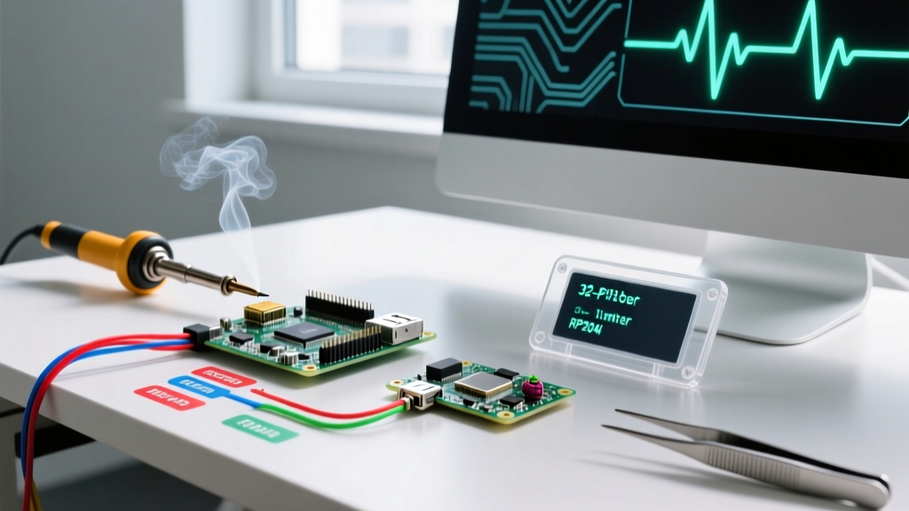

The 8-Bit Bottleneck: Why the Classic Uno Falls Short
For over a decade, the ATmega328P-based Arduino Uno has been the default launchpad for makers. However, when projects evolve from simple LED fades to precision motor control, high-frequency switching power supplies, or multi-channel RC decoding, the classic arduino pulse width functions—namely analogWrite() and pulseIn()—become critical bottlenecks.
On the standard Uno, analogWrite() is hardcoded to either 490Hz or 980Hz. Pins 5 and 6 operate at 980Hz to protect the millis() timer, while pins 3, 9, 10, and 11 default to 490Hz. Furthermore, you are strictly limited to 8-bit resolution (256 discrete steps). For a 12V LED strip, 256 steps result in visible 'stepping' or flickering at the lower dimming ranges. Similarly, pulseIn() is a blocking function; measuring a standard 20ms RC servo pulse locks the main CPU loop for 20,000 microseconds, starving other tasks and causing jitter in time-sensitive applications.
To achieve true precision, modern makers must migrate to 32-bit architectures. This guide details the hardware and software migration path from 8-bit AVR limitations to the advanced hardware timers found in the ESP32-S3 and Raspberry Pi RP2040.
Migrating Pulse Width Generation (PWM)
Upgrading your pulse width generation requires moving away from software-emulated or basic timer interrupts toward dedicated hardware peripherals that operate entirely independent of the main CPU cores.
ESP32-S3: The LEDC Peripheral
The ESP32 family utilizes the LED Control (LEDC) peripheral. Unlike the AVR's 8-bit limit, the Espressif LEDC API supports up to 14-bit resolution (16,384 steps) and frequencies up to 40MHz (though practically limited to 20kHz-40kHz for motor drivers to avoid switching losses). The ESP32-S3-DevKitC-1 (typically $7.50) offers 8 independent LEDC channels, allowing complex multi-axis robotics without timer collisions.
RP2040: Hardware PWM Slices
The Raspberry Pi Pico ($4.00) features 8 identical PWM slices, each with two channels (16 total). According to the official RP2040 datasheet, each slice features a 16-bit counter and a fractional divider. This allows you to dial in exact frequencies—such as 16.384kHz for ultrasonic transducers—with zero CPU overhead once configured.
Architecture Comparison Matrix
| Feature | Arduino Uno R3 (ATmega328P) | Arduino Uno R4 Minima | ESP32-S3-DevKitC-1 | Raspberry Pi Pico (RP2040) |
|---|---|---|---|---|
| Architecture | 8-bit AVR | 32-bit ARM Cortex-M4 | 32-bit Dual-Core Xtensa LX7 | 32-bit Dual-Core Cortex-M0+ |
| PWM Resolution | 8-bit (256 steps) | 8-bit to 12-bit | Up to 14-bit (16,384 steps) | 16-bit (65,536 steps) |
| Default Frequency | 490Hz / 980Hz | 490Hz (configurable) | 5kHz (configurable to 40MHz) | 125MHz base (configurable) |
| Independent Channels | 6 (shared timers) | 6 | 8 | 16 (8 slices) |
| Approx. Board Cost | $27.00 (Clone) / $27.50 (Official) | $27.50 | $7.50 | $4.00 |
Upgrading Pulse Width Measurement
Measuring incoming pulse widths—such as reading an ultrasonic sensor (HC-SR04), a tachometer, or an RC receiver—is where 8-bit boards truly struggle due to the blocking nature of the standard pulseIn() function.
ESP32: PCNT and RMT Peripherals
When migrating to the ESP32, abandon pulseIn() entirely. Instead, utilize the Pulse Counter (PCNT) module for high-frequency RPM measurements, or the Remote Control (RMT) peripheral for decoding complex pulse-width protocols like SBUS, PPM, or WS2812B LED timing. The RMT peripheral captures the exact duration of high and low states in hardware FIFO buffers, triggering an interrupt only when a complete frame is received. This reduces CPU load from 90% (using blocking loops) to less than 1%.
RP2040: Programmable I/O (PIO)
The RP2040's secret weapon is the PIO (Programmable I/O) state machine. You can write a micro-program that runs on a dedicated PIO core, measuring pulse widths with single-clock-cycle precision. At 125MHz, the PIO can resolve pulse widths down to 8 nanoseconds. This is invaluable for applications like time-of-flight lidar sensors or high-speed encoder decoding, where even a standard hardware interrupt latency of 2-3 microseconds introduces unacceptable jitter.
Real-World Edge Cases & Failure Modes
Hardware migrations introduce new electrical and logical pitfalls. Be prepared for the following edge cases:
- Motor Driver Beat Frequencies: If you migrate an RC car from an Uno (490Hz) to an ESP32 but forget to update the PWM frequency, your DRV8871 motor driver may emit an audible high-pitched whine and suffer from inefficient thermal dissipation. Always set motor control PWM between 16kHz and 20kHz to push switching noise above human hearing and optimize MOSFET gate charging.
- Logic Level Mismatches: The classic Uno operates at 5V logic. The ESP32-S3 and RP2040 are strictly 3.3V. Feeding a 5V pulse width signal from an RC receiver directly into an ESP32 GPIO will degrade the silicon over time or cause immediate latch-up. You must integrate a bidirectional logic level shifter (e.g., TXS0108E, approx. $2.50) or use a simple voltage divider (1kΩ and 2kΩ resistors) for unidirectional inputs.
- RTOS Watchdog Timeouts: If you attempt to use the legacy
pulseIn()function with a 30ms timeout inside an ESP32 FreeRTOS task, you risk starving the Idle Task. This prevents the system from feeding the Task Watchdog Timer (TWDT), resulting in a continuous boot-loop. Always use hardware capture or non-blocking interrupts in RTOS environments.
Step-by-Step Migration Checklist
- Audit Existing Code: Search your legacy codebase for all instances of
analogWrite()andpulseIn(). Map out which hardware timers they are currently consuming. - Select Target Hardware: Choose ESP32-S3 for wireless integration and high-resolution LEDC, or RP2040 for ultra-low-cost, high-precision PIO state machines.
- Implement Level Shifting: Verify the voltage domains of all external sensors and drivers. Add 3.3V-to-5V level shifters where necessary.
- Refactor Generation: Replace
analogWrite(pin, duty)withledcSetup(channel, freq, resolution)andledcWrite(channel, duty)for ESP32, or configure PWM slices via the Pico SDK / Arduino Mbed core. - Refactor Measurement: Replace blocking measurements with interrupt-driven Input Capture (AVR), PCNT/RMT (ESP32), or PIO (RP2040).
- Verify with Oscilloscope: Do not trust serial monitor outputs for timing. Probe the GPIO pins with a logic analyzer or oscilloscope to verify the exact rise/fall times and ensure no software jitter has been introduced.
Pro Tip: When using the Arduino IDE for 32-bit boards, ensure you have updated the ESP32 Board Manager package to version 3.x or the Arduino Mbed OS RP2040 core to the latest 2026 release. Older cores lack full support for the ESP32-S3's extended GPIO matrix and the RP2040's advanced PIO wrappers.
Migrating your arduino pulse width routines from 8-bit software emulation to 32-bit hardware peripherals is the defining line between a hobbyist prototype and a robust, production-ready embedded system. By leveraging the LEDC, RMT, and PIO peripherals, you unlock microsecond precision, eliminate CPU blocking, and future-proof your designs for the most demanding applications.