
Integrating a potentiometer and Arduino is one of the most fundamental tasks in electronics prototyping, yet it is fraught with hidden hardware quirks and software inefficiencies. Whether you are building a MIDI controller, tuning a PID loop, or simply dimming an LED, understanding the underlying Analog-to-Digital Converter (ADC) architecture and signal conditioning is critical. This quick reference FAQ bypasses the fluff and delivers actionable, expert-level troubleshooting and design frameworks for your next project.
Quick Reference: Potentiometer and Arduino Specs
Before wiring your circuit, review the hardware specifications below. Note the differences between the classic ATmega328P architecture and the modern Renesas-based boards.
| Parameter | Standard Uno R3 (ATmega328P) | Uno R4 Minima/WiFi (RA4M1) |
|---|---|---|
| ADC Resolution | 10-bit (0-1023) | 12-bit / 14-bit (up to 16383) |
| Recommended Pot Value | 10KΩ Linear (B-Taper) | 10KΩ Linear (B-Taper) |
| Max Source Impedance | 10KΩ | ~50KΩ (Lower is better) |
| VCC / GND Pins | 5V / GND | 5V / GND |
| Signal Pin | A0 - A5 | A0 - A5 |
Hardware & Wiring FAQ
Why is 10KΩ the standard potentiometer value?
The recommendation for a 10KΩ potentiometer (such as the popular Alpha RD901F or Bourns panel-mount series) is not arbitrary; it is dictated by the microcontroller's internal ADC architecture. The ATmega328P ADC utilizes a sample-and-hold (S/H) circuit featuring an internal sampling capacitor of approximately 14pF. During the sampling phase (which lasts about 1.5 ADC clock cycles), this capacitor must charge to match the input voltage at the wiper.
If you use a high-resistance potentiometer (e.g., 100KΩ or 1MΩ), the RC time constant becomes too large. The internal capacitor cannot fully charge before the conversion begins, resulting in non-linear, lower-than-expected readings, especially at the extremes of the rotation. A 10KΩ pot provides the optimal balance: low enough impedance for accurate ADC charging, but high enough to prevent excessive current draw (only 0.5mA at 5V).
Linear (B) vs. Audio (A) Taper: Which do I need?
When pairing a potentiometer and Arduino for sensor input, always choose a Linear Taper (marked with a 'B', e.g., B10K). In a linear pot, the resistance changes at a constant rate relative to shaft rotation, mapping perfectly to the Arduino's analogRead() function.
Audio Taper (marked with an 'A', logarithmic) pots are designed to match human hearing perception in analog volume controls. If you use an A-taper pot with an Arduino, the first 50% of the physical rotation will only yield about 10-15% of the ADC value range, making precise digital control in the lower half nearly impossible. For a deep dive into taper curves and resistive track geometries, refer to the potentiometer taper characteristics on Wikipedia.
Trimpots vs. Panel Mount: Which should I use?
For breadboard prototyping and calibration, use a Bourns 3296W multi-turn trimpot. Unlike single-turn trimmers, the 3296W requires 25 full turns to sweep the entire resistance range, allowing for microscopic adjustments when tuning sensor thresholds. For user-facing interfaces (knobs, dials), use a panel-mount pot with a metal shaft and a grounding lug to prevent electrostatic interference.
Code, ADC Resolution, and Signal Processing
How do I handle different ADC resolutions?
The classic Arduino Uno R3 uses a 10-bit ADC, returning values from 0 to 1023. However, modern boards like the Uno R4 Minima feature a 14-bit ADC. By default, analogRead() might still return 10-bit values for backward compatibility, but you can unlock the full 14-bit range (0-16383) for much finer control in precision applications like synthesizer tuning or robotic arm positioning.
// Uno R4 14-bit ADC setup
analogReadResolution(14);
int rawValue = analogRead(A0); // Returns 0 to 16383
For the standard Arduino analogRead() reference, always remember that the function reads the voltage relative to the board's active reference pin (default 5V or 3.3V depending on the board).
How do I eliminate ADC jitter and noise?
Even with a perfect 10KΩ pot, environmental noise, USB power ripple, and unshielded jumper wires can cause the analogRead() value to fluctuate by ±5 to ±15 points. While the standard Arduino Smoothing example uses an array-based moving average, this consumes unnecessary SRAM and introduces phase lag in control loops.
Instead, use an Exponential Moving Average (EMA) filter. It requires only one float variable, executes in microseconds, and provides buttery-smooth data.
const float ALPHA = 0.05; // Smoothing factor (0.01 to 0.1)
float smoothedValue = 0;

void setup() {
  Serial.begin(115200);
  smoothedValue = analogRead(A0); // Initialize
}

void loop() {
  int raw = analogRead(A0);
  // EMA Formula: S_t = S_t-1 + ALPHA * (X_t - S_t-1)
  smoothedValue = smoothedValue + ALPHA * (raw - smoothedValue);
  Serial.println(smoothedValue);
  delay(10);
}
Troubleshooting Common Edge Cases
My reading is stuck at 1023 (or the maximum value)
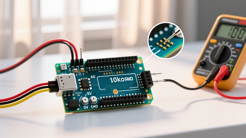
This almost always indicates a floating signal pin. The wiper (middle pin) of the potentiometer is either disconnected, suffering from a cold solder joint, or plugged into a digital pin instead of an analog pin. The Arduino's internal pull-up/pull-down leakage or stray electromagnetic interference drives the high-impedance ADC input to the rail. Verify continuity from the wiper to the A0 pin using a multimeter.
The values are erratic only when I touch the metal shaft
Your body is acting as an antenna, injecting 50/60Hz mains hum into the circuit. This happens frequently with ungrounded metal-shaft potentiometers.
Pro-Tip Fix:
1. Add a 100nF (0.1µF) ceramic decoupling capacitor directly between the wiper pin and GND, as close to the Arduino header as possible. This creates a hardware low-pass filter.
2. If the pot has a metal casing and a dedicated ground lug, wire the lug directly to the Arduino GND to shield the internal resistive track.
Why does the reading jump when I add a motor or servo?
Motors and servos cause massive voltage sags and high-frequency noise on the 5V rail. Because the Arduino's ADC measures voltage relative to the 5V rail, any dip in the 5V rail instantly skews the potentiometer reading.
Actionable Solution: Do not power servos directly from the Arduino's 5V pin. Use a dedicated external 5V/6A buck converter for high-draw actuators, and ensure a common ground is established between the external power supply and the Arduino GND.
Ratiometric Measurement: Why VCC fluctuations usually don't matter
A potentiometer acts as a voltage divider. If the Arduino's 5V rail drops to 4.8V under load, the voltage at the wiper drops proportionally. Because the ADC's reference voltage is also tied to that same 5V rail, the digital output (0-1023) remains perfectly accurate. This is known as ratiometric measurement. However, if you use analogReference(EXTERNAL) with a precision 4.096V reference IC, the pot reading will now fluctuate wildly if the 5V VCC rail sags. Always tie your pot's VCC to the exact same voltage source as your ADC reference.