
The Anatomy of a 7-Segment Display
Configuring a 7 segment arduino setup is a rite of passage for embedded systems engineers and hobbyists alike. However, what seems like a simple component quickly reveals underlying complexities regarding current sourcing, pin multiplexing, and refresh rate management. Before writing a single line of code, you must understand the internal topology of your display.
7-segment displays (often packaged as 4-digit modules like the 5461AS or 5461BS) come in two primary configurations:
- Common Cathode (CC): All LED cathodes are tied together and connected to Ground (GND). You illuminate a segment by driving the corresponding anode pin HIGH (5V).
- Common Anode (CA): All LED anodes are tied together and connected to VCC (5V). You illuminate a segment by driving the corresponding cathode pin LOW (GND).
The Resistor Math and MCU Pin Limits
A critical failure point in DIY projects is skipping current-limiting resistors or miscalculating their values. According to SparkFun's LED engineering guidelines, driving an LED without a resistor will cause thermal runaway, destroying both the LED and the microcontroller's GPIO pin.
Let's calculate the exact resistor value for a standard red 7-segment display powered by a 5V Arduino Uno Rev3:
- Source Voltage ($V_s$): 5.0V
- LED Forward Voltage ($V_f$): 2.0V (Red)
- Target Forward Current ($I_f$): 20mA (0.02A)
Using Ohm's Law: $R = (V_s - V_f) / I_f$
$R = (5.0 - 2.0) / 0.02 = 150\Omega$.
CRITICAL E-E-A-T WARNING: The ATmega328P microcontroller on the Arduino Uno has an absolute maximum current rating of 40mA per I/O pin, and a total VCC/GND package limit of 200mA. If you are multiplexing a 4-digit display directly without driver transistors, the peak current during the 25% duty cycle can easily exceed 40mA per segment pin, leading to permanent silicon degradation. Always use driver ICs or NPN/PNP transistor arrays for direct multiplexing.
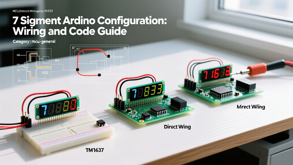
Configuration Matrix: Direct vs. TM1637 vs. MAX7219
In 2026, the maker market offers highly integrated driver ICs that eliminate the need for messy transistor arrays and complex timer-interrupt multiplexing code. Below is a technical comparison of the three most common configuration paths.
| Configuration Method | Arduino Pins Required | Hardware Complexity | Approx. Module Cost (2026) | Best Use Case |
|---|---|---|---|---|
| Direct GPIO (Multiplexed) | 11 Pins (7 segments + 4 digits) | High (Requires 4x NPN transistors, 11x resistors) | $1.20 (Raw components) | Custom PCB designs, learning MCU timers |
| TM1637 Driver IC | 2 Pins (CLK, DIO) | Low (Plug-and-play module) | $1.50 - $2.00 | Clock displays, basic sensor readouts |
| MAX7219 Driver IC (SPI) | 3 Pins (DIN, CLK, CS) | Medium (Requires decoupling capacitors) | $2.50 - $3.50 | High-speed counters, daisy-chained matrices |
Step-by-Step Configuration: TM1637 4-Digit Module
The TM1637 is a specialized LED driver that communicates via a proprietary 2-wire I2C-like protocol. It handles all multiplexing and brightness control internally, freeing your Arduino's CPU for core logic.
Hardware Wiring
- Connect VCC to Arduino 5V.
- Connect GND to Arduino GND.
- Connect CLK to Digital Pin 2.
- Connect DIO to Digital Pin 3.
Software Configuration
Install the TM1637Display library via the Arduino Library Manager. The following sketch initializes the display, sets maximum brightness, and creates a simple stopwatch using non-blocking millis() timing.
#include

#define CLK 2
#define DIO 3

TM1637Display display(CLK, DIO);
unsigned long previousMillis = 0;
int counter = 0;

void setup() {
  // Set brightness (0x0f is maximum, 0x00 is minimum)
  display.setBrightness(0x0f);
  display.showNumberDec(0, false);
}

void loop() {
  unsigned long currentMillis = millis();
  if (currentMillis - previousMillis >= 1000) {
    previousMillis = currentMillis;
    counter++;
    // Display with leading zeros disabled
    display.showNumberDec(counter, false);
  }
}
Advanced Configuration: MAX7219 via SPI
For applications requiring high-speed updates or daisy-chaining multiple modules, the MAX7219 is the industry standard. It utilizes the SPI bus, which is significantly faster than the TM1637's custom protocol. For deeper integration with Arduino's native hardware SPI bus, refer to the official Arduino SPI reference documentation.
The Decoupling Capacitor Rule
A frequent cause of MAX7219 initialization failure is missing decoupling capacitors. The MAX7219 datasheet strictly mandates a 10µF electrolytic capacitor and a 0.1µF ceramic capacitor placed as close to the V+ and GND pins as physically possible. When the display updates multiple segments simultaneously, it draws sudden current spikes that can cause the internal logic to reset or display garbage data if the local power rail sags.
Wiring and Code Implementation
- VCC: 5V (Ensure your Arduino's 5V rail can supply at least 300mA for an 8x8 matrix or 4-digit display at full brightness).
- GND: GND
- DIN: Pin 11 (MOSI on Uno)
- CLK: Pin 13 (SCK on Uno)
- CS (LOAD): Pin 10 (SS on Uno)
Using the popular LedControl library, configuration is straightforward:
#include

// Pins: DIN=11, CLK=13, CS=10, Max Devices=1
LedControl lc = LedControl(11, 13, 10, 1);

void setup() {
  // Wake up the MAX7219 from power-saving mode
  lc.shutdown(0, false);
  // Set medium brightness (0-15)
  lc.setIntensity(0, 8);
  lc.clearDisplay(0);
}

void loop() {
  for (int i = 0; i < 10000; i++) {
    lc.setDigit(0, 3, (i / 1000) % 10, false);
    lc.setDigit(0, 2, (i / 100) % 10, false);
    lc.setDigit(0, 1, (i / 10) % 10, false);
    lc.setDigit(0, 0, i % 10, false);
    delay(50);
  }
}
Real-World Failure Modes and Troubleshooting
Even with driver ICs, 7-segment configurations can exhibit erratic behavior. Here is how to diagnose the most common edge cases encountered in the field.
1. Display Ghosting and Bleed-Over
Symptom: Faint illumination of segments that should be off, particularly when transitioning between numbers (e.g., an '8' leaving a faint ghost when changing to a '1').
Root Cause: In direct-wired multiplexed setups, this occurs when the segment pins are not turned off before the digit select pin switches to the next common pin. The brief overlap causes current to bleed into the previous digit.
Solution: Implement a 'blanking' phase in your code. Turn off all segment pins, switch the digit common pin, wait 1-2 microseconds, then apply the new segment data. If using the SevSeg Arduino Library for direct wiring, ensure the setCommonCathode() or setCommonAnode() flag perfectly matches your hardware.
2. Severe Flickering Under Load
Symptom: The display flickers noticeably to the human eye, especially when the Arduino is executing heavy sensor polling or wireless (Wi-Fi/BLE) tasks.
Root Cause: Direct multiplexing relies on the main loop() executing fast enough to maintain a >60Hz refresh rate (Persistence of Vision). If a blocking function like delay() or a slow I2C sensor read stalls the loop, the refresh rate drops below the human flicker fusion threshold.
Solution: Offload multiplexing to a hardware timer interrupt (e.g., using the TimerOne library) so the display refreshes independently of the main code execution. Alternatively, switch to a TM1637 or MAX7219 module, which handles multiplexing entirely in hardware.
3. Dim or Uneven Brightness
Symptom: The display is too dim to read in ambient light, or certain digits appear brighter than others.
Root Cause: Power starvation. The Arduino's onboard 5V linear regulator (typically an NCP1117 or similar) can only safely supply 500mA to 800mA, and much of that is lost as heat. If you are driving a large 7-segment display array directly from the Arduino 5V pin, voltage sag will occur.
Solution: Bypass the Arduino's onboard regulator. Supply 5V directly to the display module's VCC pin using a dedicated external buck converter (like an LM2596 module set to 5.0V), ensuring the external GND is tied to the Arduino GND to maintain a common logic reference.