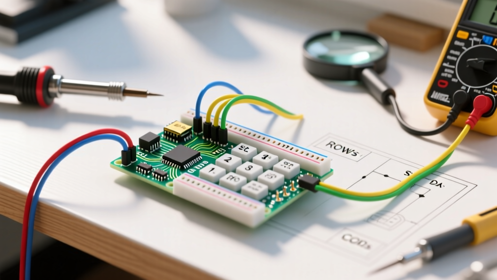

Understanding Keypad Arduino Architectures
Integrating a keypad into your microcontroller project is a rite of passage for makers, but not all keypads communicate with all boards in the same way. When evaluating keypad Arduino compatibility, you are generally choosing between two distinct hardware architectures: direct passive matrix arrays and active I2C-based keypad scanners. In 2026, with the maker ecosystem heavily favoring 3.3V logic boards like the ESP32-S3 and Raspberry Pi Pico (RP2040), understanding the electrical nuances of these interfaces is critical to avoid fried pins and unresponsive buttons.
This compatibility guide breaks down the exact wiring schemes, microcontroller-specific traps, and library ecosystems for standard 3x4 and 4x4 membrane keypads, ensuring your next input interface works flawlessly on the first upload.
Direct Matrix Keypads: The 3x4 and 4x4 Standard
The most common keypads on the market are passive membrane matrices. A standard 3x4 keypad (12 keys) features 7 output pins, while a 4x4 keypad (16 keys) features 8 pins. These keypads do not require external power; instead, they rely on the microcontroller to sequentially scan rows and columns to detect button presses.
Pinout Compatibility & Wiring Strategy
To interface a direct matrix keypad, you must configure your microcontroller pins to alternate between outputs and inputs. The standard approach, supported by the ubiquitous Keypad.h library, involves:
- Rows (e.g., Pins 1-4): Configured as digital
OUTPUT. The microcontroller drives one rowLOWat a time while keeping the othersHIGH. - Columns (e.g., Pins 5-7): Configured as digital
INPUT_PULLUP. The microcontroller reads the columns; if a column readsLOWwhile a specific row is drivenLOW, the intersecting key is pressed.
Pro Tip: Never use external 5V pull-up resistors on the column lines if you are using a 3.3V microcontroller. Rely strictly on the internal INPUT_PULLUP configuration to prevent 5V logic from back-feeding into 3.3V GPIO pins.
The ESP32 and RP2040 Compatibility Trap
While an Arduino Uno (ATmega328P) allows you to use almost any digital pin for a matrix keypad, modern 3.3V boards have strict hardware limitations that catch many beginners off guard.
| Microcontroller | Voltage Logic | GPIO Constraints for Matrix Keypads | Compatibility Verdict |
|---|---|---|---|
| Arduino Uno / Nano | 5V | None. All digital pins support bidirectional I/O and internal pull-ups. | Excellent |
| ESP32 (Standard) | 3.3V | GPIO 34, 35, 36, and 39 are input-only and lack internal pull-up resistors. Do not use these for column reads. | Good (with pin planning) |
| Raspberry Pi Pico | 3.3V | GPIO 26-28 share ADC functionality but work fine as digital I/O with internal pull-ups. | Excellent |
| Arduino Nano 33 BLE | 3.3V | All pins are bidirectional, but 3.3V logic requires clean contacts; membrane degradation causes read errors faster here. | Good |
I2C Keypad Expanders: Saving GPIO Pins
If your project requires a keypad but you are starved for GPIO pins (or building a custom PCB where routing 8 traces is impractical), I2C keypad expanders are the professional solution. By shifting the scanning logic off the main microcontroller, you reduce the wiring to just four lines: VCC, GND, SDA, and SCL.
PCF8574 vs. TCA8418: Which Expander to Choose?
Not all I2C expanders are created equal. When sourcing components in 2026, you will primarily encounter two chips:
- PCF8574 (Generic I/O Expander): Priced around $0.80 to $1.20 per module, this is a basic 8-bit I/O expander. It does not natively understand 'keypads'; it simply reads and writes pin states. You must still use a software library to perform the matrix scanning over the I2C bus. It is cheap but adds slight I2C bus overhead during rapid scanning.
- TCA8418 (Dedicated Keypad Scanner): Priced around $4.95 (commonly found on Adafruit breakouts), this chip is a purpose-built keypad encoder. It handles matrix scanning internally, features a built-in FIFO buffer to store up to 10 keypress events, and includes an
INT(interrupt) pin. This allows your Arduino to sleep and only wake up when a physical key is pressed, making it the ultimate choice for battery-powered IoT devices.
For a comprehensive look at how the I2C protocol handles these communications, refer to the official Arduino Wire Library Documentation, which details the bus speed and buffer limitations inherent to I2C expanders.
Hardware Failure Modes: Ghosting and Contact Degradation
A common complaint in maker forums is 'ghosting' or 'shadowing'—a phenomenon where pressing two keys simultaneously registers a third, phantom keypress. This occurs in direct matrix keypads when current back-feeds through the closed switches, creating an unintended short circuit path across the grid.
The Diode Fix for N-Key Rollover
If your application requires pressing multiple keys at once (such as a chorded keyboard or a gaming macro pad), standard membrane keypads will fail you. To achieve true N-Key Rollover (NKRO), you must solder a standard 1N4148 switching diode in series with every single key switch, ensuring the cathode (stripe) points toward the column line. This enforces unidirectional current flow, entirely eliminating ghosting.
Furthermore, cheap membrane keypads (often priced under $1.50 on bulk marketplaces) suffer from carbon pad degradation. After roughly 10,000 actuations, the contact resistance can climb from 10 ohms to over 500 ohms. On 5V Arduinos, this is rarely an issue. However, on 3.3V logic boards, this increased resistance can cause the voltage to sag below the LOW threshold, resulting in missed keystrokes. For high-reliability 3.3V projects, invest in rigid PCB-backed tactile keypads (typically $4.00 - $6.00) rather than flexible PET membranes.
Library Compatibility & Debouncing
Hardware is only half the battle; software compatibility dictates your development speed. The community standard for direct matrix scanning remains the Keypad library by Mark Stanley and Alexander Brevig, hosted on the Arduino Playground. It is highly optimized for AVR and standard ARM Cortex-M boards.
However, if you are using modern I2C expanders or advanced switch matrices, the Adafruit_Keypad library offers superior event-driven architecture. Unlike the blocking nature of older polling loops, modern libraries utilize hardware timers and interrupt service routines (ISRs) to handle debouncing.
Debouncing Timings by Switch Type
- Standard Membrane (PET): 10ms - 15ms debounce delay.
- Mechanical Tactile (6x6mm): 20ms - 30ms debounce delay.
- Cherry MX / Kailh Low Profile: 5ms - 10ms debounce delay (requires diode matrix for accuracy).
Frequently Asked Questions
Can I use a 5V keypad with a 3.3V ESP32?
Yes, but with caveats. The keypad itself is passive and does not care about voltage. However, you must ensure your ESP32 provides the 3.3V logic for the INPUT_PULLUP states. Do not connect external 5V pull-up resistors to the keypad traces, or you will feed 5V directly into the ESP32's 3.3V-tolerant GPIO pins, potentially destroying the silicon.
Why is my 4x4 keypad only registering the first row?
This is almost always a wiring or pin-definition mismatch. The standard pinout for a 4x4 membrane keypad reads from left to right as Row 1, Row 2, Row 3, Row 4, Col 1, Col 2, Col 3, Col 4. If you accidentally map a column pin to a row definition in your software array, the scanning algorithm will fail to detect intersections beyond the first row. Verify your physical trace routing with a multimeter in continuity mode.
Do I need an I2C expander for an Arduino Mega?
No. The Arduino Mega2560 has 54 digital I/O pins. You have more than enough GPIO headroom to wire a direct 4x4 matrix (8 pins) and still have ample pins for LCDs, sensors, and motor drivers. I2C expanders are best reserved for pin-starved boards like the Arduino Nano, ESP-01, or ATtiny85.
For further reading on physical button integration and matrix scanning theory, the SparkFun 12-Button Keypad Hookup Guide provides excellent visual schematics and continuity testing methodologies that complement the software configurations discussed above.