
The Anatomy of an Unwanted Arduino Restart
When a microcontroller enters a continuous reset loop, it is commonly referred to as a "bootloop." If you are trying to figure out why your project fails and need to restart Arduino hardware repeatedly to get a single successful sensor reading, you are likely dealing with a systemic fault rather than a simple code bug. In 2026, with the widespread adoption of the Arduino Uno R4 Minima and advanced ESP32-S3 modules, reset diagnostics have evolved, but the foundational physics of power delivery and memory management remain unchanged.
Diagnosing a restart requires distinguishing between a software exception (like a stack overflow) and a hardware reset event (like a brownout). This guide provides a senior-level diagnostic framework to isolate and resolve bootloop errors on AVR and ARM-based maker boards.
Diagnostic Matrix: Identifying the Reset Trigger
Before opening the serial monitor, use this matrix to correlate physical symptoms with underlying electrical or logical faults.
| Symptom Profile | Probable Root Cause | Diagnostic Tool | Hardware/Software Fix |
|---|---|---|---|
| Resets exactly when a servo/relay activates | Brown-Out Detection (BOD) / Voltage Droop | Oscilloscope or USB Power Meter ($15-$25) | Add 470µF low-ESR capacitor; use separate BEC for servos |
| Resets every 2 to 8 seconds predictably | Watchdog Timer (WDT) infinite loop | Check MCUSR register on boot | Insert wdt_reset() in main loop |
| Resets randomly after minutes of operation | SRAM Heap/Stack Collision (Memory Leak) | MemoryFree library / Stack painting | Use PROGMEM for strings; avoid String class |
| Resets when touched or near high-voltage AC | Floating RESET pin / EMI susceptibility | Visual inspection / Continuity test | Add 10kΩ pull-up resistor to 5V rail |
Deep Dive: Power Starvation and Brown-Out Detection
The most frequent cause of a bootloop in DIY robotics and home automation is power starvation. The ATmega328P-PU (the heart of the classic Uno R3) features a hardware Brown-Out Detection (BOD) circuit. By default, the BOD threshold is set via fuses to 2.7V. However, many clone boards or custom PCBs set this to 4.3V to ensure stable USB communication.
The Servo Droop Effect
When a standard SG90 micro servo stalls or starts under load, it can draw upwards of 700mA for a few milliseconds. If powered directly from the Arduino's 5V rail (which is limited to ~500mA via USB or ~800mA via the onboard linear regulator), the voltage rail will experience a transient droop. If the voltage dips below the BOD threshold for more than a few microseconds, the microcontroller will instantly execute a hardware restart.
Expert Tip: Do not rely on a standard digital multimeter to catch servo-induced voltage droops. The sampling rate is too slow. Use a digital storage oscilloscope (like a Rigol DS1054Z) with single-trigger mode set to capture falling edges below 4.5V, or use a dedicated USB power meter with min/max logging.
Tracking Restarts via the MCUSR Register
To accurately diagnose why the board is restarting, you must read the Microcontroller Unit Status Register (MCUSR) immediately upon boot, before the Arduino bootloader clears it. This register holds the "black box" data of your reset event.
According to the official Microchip ATmega328P documentation, the MCUSR contains specific flags for Power-on Reset (PORF), External Reset (EXTRF), Brown-out Reset (BORF), and Watchdog Reset (WDRF).
Implement this diagnostic snippet at the very top of your setup() function:
void setup() {
  Serial.begin(115200);
  byte mcusr = MCUSR;
  MCUSR = 0; // Clear the register

  if (mcusr & (1 << PORF)) Serial.println("Diagnosis: Power-On Reset");
  if (mcusr & (1 << EXTRF)) Serial.println("Diagnosis: External Pin Reset");
  if (mcusr & (1 << BORF)) Serial.println("Diagnosis: Brown-Out (Voltage Drop)");
  if (mcusr & (1 << WDRF)) Serial.println("Diagnosis: Watchdog Timer Timeout");
}
If your serial monitor repeatedly outputs "Diagnosis: Brown-Out", you have confirmed a power delivery failure. If it outputs "Watchdog Timer Timeout", your code is hanging.
Watchdog Timer (WDT) Traps
The Watchdog Timer is a safety mechanism designed to restart the Arduino if the main loop freezes. However, improper implementation creates an inescapable bootloop. If you enable the WDT with a 2-second timeout but place a delay(3000) or a blocking while() loop in your code, the WDT will trigger a reset before the wdt_reset() command can execute.
Worse, on older AVR bootloaders (like the Optiboot version on early Uno R3s), a WDT reset does not properly disable the watchdog timer before jumping to the user sketch. This results in an infinite bootloop where the board resets before setup() even finishes running. To resolve this, ensure you are using the latest Arduino IDE (2.3.x or newer in 2026) which flashes updated bootloaders that handle WDT states correctly, or manually clear the WDRF bit and disable the WDT as the very first instruction in your main() or setup().
SRAM Exhaustion and Stack Collisions
The ATmega328P possesses a mere 2KB of SRAM. If your sketch utilizes the String class heavily, dynamic memory allocation (heap) grows upward, while local variables (stack) grow downward. When they collide, the microcontroller overwrites critical execution pointers, resulting in a spontaneous restart.
Diagnostic Steps for Memory Leaks:
- Avoid Dynamic Allocation: Never use the
Stringobject for parsing serial data in production firmware. Use fixed-size C-arrays (char buffer[64]). - Move Constants to Flash: Wrap all static serial print statements in the
F()macro (e.g.,Serial.println(F("Sensor initialized"));) to keep them in the 32KB Flash memory rather than consuming precious SRAM. - Monitor Free RAM: Implement a lightweight
FreeMemory()function to log available SRAM to an SD card or EEPROM every minute. A steadily declining graph confirms a heap leak.
ESP32 vs. AVR: Advanced Reset Diagnostics
If your project uses an ESP32 or ESP32-S3, the diagnostic approach shifts. The ESP-IDF framework provides a highly detailed API for reset diagnosis. According to the Espressif ESP-IDF System API documentation, you can call esp_reset_reason() to retrieve an enumerated list of exact reset triggers.
Common ESP32 reset codes include:
ESP_RST_BROWNOUT: The internal software brownout detector triggered (often due to Wi-Fi transmission spikes drawing 300mA+).ESP_RST_TASK_WDT: The Task Watchdog Timer caught a high-priority FreeRTOS task starving the idle task.ESP_RST_PANIC: A severe software exception, such as a null pointer dereference or stack overflow, occurred.
For ESP32 brownouts, the fix rarely involves just adding a capacitor. You must often configure the Wi-Fi transmit power down via esp_wifi_set_max_tx_power() to reduce peak current draw, or disable the software brownout detector in the sdkconfig file if you have robust external power regulation.
Hardware Mitigation: Taming EMI and Floating Pins
In industrial environments or near AC mains, electromagnetic interference (EMI) can couple into the PCB traces. The RESET pin on an AVR is active-low. If the trace is long and lacks a pull-up resistor, a spike of EMI can pull the pin below the logic-low threshold (0.3 * VCC), triggering an external reset.
While the official Arduino Troubleshooting Guide recommends checking USB cables and drivers for upload failures, hardware instability requires physical layer fixes:
- Solder a 10kΩ pull-up resistor between the RESET pin and the 5V rail.
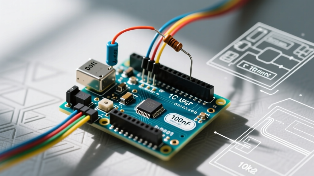
- Add a 100nF X7R ceramic capacitor as close to the VCC and GND pins of the microcontroller as physically possible to filter high-frequency noise.
- Ensure the USB cable is shielded. Unshielded $2 cables act as antennas for EMI, causing the CH340G or ATmega16U2 USB-to-Serial chip to falsely assert the DTR (Data Terminal Ready) line, which is hardwired to the auto-reset circuit.
Summary: A Methodical Approach
When you need to restart Arduino boards to recover from a freeze, you are treating the symptom, not the disease. By reading the MCUSR register, measuring transient voltage droops, and enforcing strict SRAM management, you can transform an unstable prototype into a deployment-ready embedded system. Always isolate power rails for high-draw inductive loads, and let the silicon's internal diagnostic registers guide your debugging process.