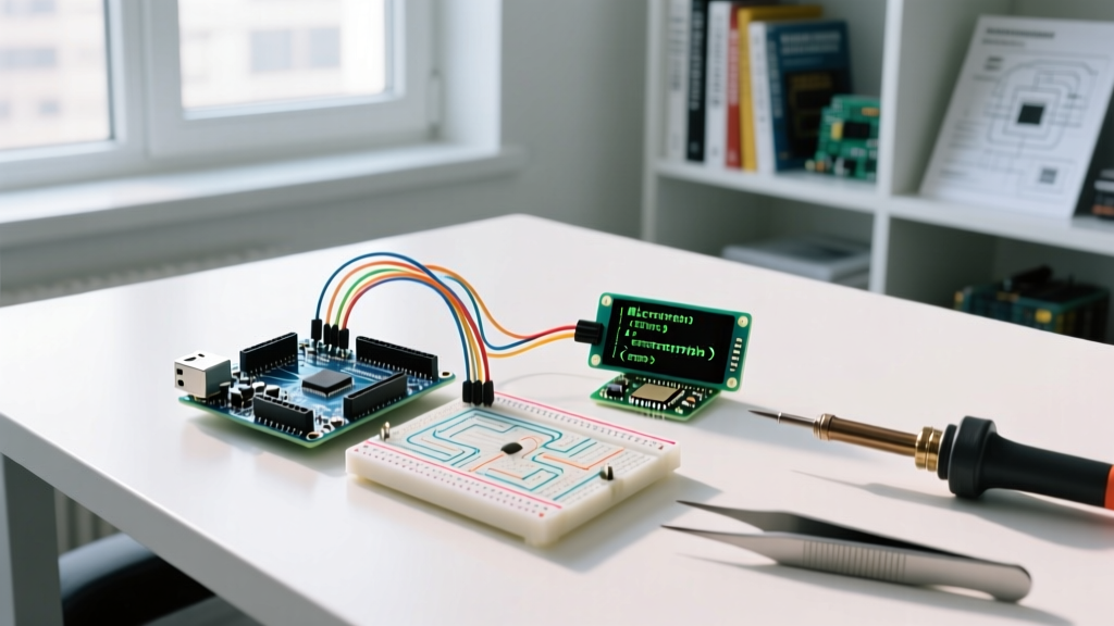
Your Practical Intro to Arduino: Beyond the Basics
Welcome to your definitive, hands-on intro to Arduino. If you are reading this in 2026, the microcontroller landscape has shifted dramatically. While the classic AVR-based boards are still legendary, modern maker projects increasingly rely on ARM Cortex-M4 and RISC-V architectures for native USB HID, floating-point math, and higher clock speeds. This tutorial skips the vague theory and drops you straight into a professional-grade hardware setup, wiring, and deployment workflow using the modern standard: the Arduino Uno R4 Minima.
Phase 1: Selecting the Right Board for 2026
Before writing a single line of C++, you must choose the right silicon. The term 'Arduino' refers to the ecosystem, not just one board. Below is a quick comparison of the three most relevant entry-level boards available today.
| Board Model | Microcontroller | Clock Speed | Logic Level | Approx. Price |
|---|---|---|---|---|
| Uno R3 (Classic) | ATmega328P (AVR) | 16 MHz | 5V | $27.00 |
| Uno R4 Minima | Renesas RA4M1 (ARM) | 48 MHz | 5V Tolerant | $20.00 |
| Nano ESP32 | ESP32-S3 (Xtensa) | 240 MHz | 3.3V | $21.00 |
For this tutorial, we are using the Arduino Uno R4 Minima (SKU: ABX00080). It retains the exact physical footprint and pinout of the classic R3, meaning all legacy shields fit perfectly, but it upgrades the brain to a 32-bit ARM Cortex-M4. It also features a native USB-C connector and a built-in 12x8 LED matrix, eliminating the need for external displays in early prototyping.
Phase 2: IDE Configuration and Board Management
The Arduino IDE 2.3.x series is the current standard. It features a modernized UI, real-time autocomplete, and an integrated serial plotter.
Step-by-Step Environment Setup
- Download the IDE: Navigate to the official Arduino software page and download the native installer for your OS (Windows, macOS, or Linux).
- Install Core Packages: Open the IDE, click the 'Boards Manager' icon on the left sidebar, and search for
Arduino Renesas RA4M1. Install the latest package to ensure your OS recognizes the R4's native USB CDC. - Connect and Verify: Plug your Uno R4 Minima into your PC using a high-quality, data-capable USB-C cable. (Warning: Many cheap cables are 'charge-only' and lack the D+/D- data lines required for serial communication).
- Select Port: Go to Tools > Port and select the COM port (Windows) or
/dev/cu.usbmodem...(macOS) labeled 'Arduino Uno R4 Minima'.
Phase 3: Wiring Your First External Circuit
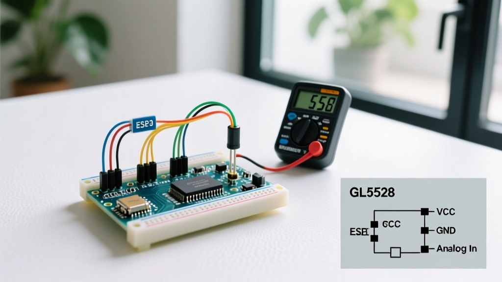
While the R4 features an onboard LED matrix, a proper intro to Arduino requires understanding external GPIO (General Purpose Input/Output) wiring. We will build a classic 'Blink' circuit using an external 5mm through-hole LED.
The Engineering Behind the Wiring (Ohm's Law)
Never connect an LED directly to a microcontroller pin without a current-limiting resistor. The Uno R4 Minima's GPIO pins can source up to 8mA safely per pin (with a total VCC limit of 60mA). A standard red 5mm LED has a forward voltage (Vf) of roughly 2.0V and an optimal forward current (If) of 20mA.
Pro-Tip: Calculating the Resistor
Using the 5V output pin to power the LED, the voltage drop across the resistor must be 3.0V (5.0V - 2.0V).
R = V / I
R = 3.0V / 0.020A = 150Ω
Since 150Ω is a non-standard E12 value, we round up to the next standard size: 220Ω. This limits current to a very safe ~13.6mA, extending the LED's lifespan and protecting the ARM silicon.
Physical Wiring Steps
- Step 1: Insert the 220Ω resistor into the breadboard. Connect one leg to Digital Pin 8 on the Arduino using a male-to-male jumper wire.
- Step 2: Connect the other leg of the resistor to the Anode (the longer leg) of the 5mm LED.
- Step 3: Connect the Cathode (the shorter leg, flat side of the bulb) to the GND (Ground) pin on the Arduino.
Phase 4: Writing and Compiling the Sketch
In the Arduino ecosystem, code files are called 'sketches'. Open a new sketch and input the following optimized C++ code. Notice the use of const and pinMode best practices, which are critical for memory management on embedded systems.
// Define the pin mapping using constant integers to save RAM
const int LED_PIN = 8;

void setup() {
  // Initialize the digital pin as an output
  pinMode(LED_PIN, OUTPUT);

  // Optional: Initialize serial communication for debugging
  Serial.begin(115200);
  while (!Serial) {
    ; // Wait for serial port to connect (Native USB)
  }
  Serial.println("System Initialized. Blinking external LED.");
}

void loop() {
  digitalWrite(LED_PIN, HIGH);  // Turn the LED on (5V logic high)
  delay(500);                   // Wait 500 milliseconds
  digitalWrite(LED_PIN, LOW);   // Turn the LED off (0V logic low)
  delay(500);                   // Wait 500 milliseconds
}
Click the Verify button (checkmark icon) to compile. The IDE will run the GCC ARM toolchain in the background, translating your C++ into machine code specific to the Renesas RA4M1. Check the output console; a successful compile will show the exact flash memory and RAM usage percentages.
Phase 5: Uploading and Edge-Case Troubleshooting
Click the Upload button (right-pointing arrow). The IDE will compile and push the binary via the USB CDC protocol. Your external LED should immediately begin blinking at a 1Hz frequency.
What If the Upload Fails? (The 'Greyed Out' Port Issue)
A common failure mode for beginners occurs when a sketch crashes the USB stack or utilizes deep sleep modes, causing the board to disappear from the OS device manager. The IDE's port selection will grey out. According to the official Arduino documentation, you can force the board back into bootloader mode using the '1200 bps touch' trick:
- Locate the Reset Button: Find the small red tactile switch near the USB-C port on the Uno R4.
- The Double-Tap Sequence: Quickly press and release the reset button twice in rapid succession (within 500ms).
- Observe the Onboard LED: The green 'L' LED will pulse slowly. This indicates the Renesas bootloader is active and waiting for a new binary.
- Re-select the Port: The COM port number may temporarily change (e.g., from COM3 to COM4). Select the new port in the IDE and click Upload again.
Next Steps: Expanding Your Hardware Knowledge
Congratulations, you have successfully completed a modern intro to Arduino hardware and software deployment. You have navigated IDE configuration, applied Ohm's law to protect sensitive ARM silicon, and learned critical bootloader recovery techniques.
To continue your journey, your next logical step is to explore analog inputs using potentiometers and photoresistors, or to integrate I2C sensors like the BME280 for environmental data logging. For further reading on advanced circuit design and microcontroller architectures, consult resources like the SparkFun Learn portal, which offers excellent deep-dives into embedded electronics and schematic reading.
Remember: the best way to master microcontrollers is through iterative failure and debugging. Keep your multimeter handy, always double-check your ground connections, and never bypass current-limiting resistors.