
Why Choose Arduino and Ethernet in 2026?
While wireless microcontrollers like the ESP32 dominate hobbyist IoT projects, pairing an Arduino and Ethernet remains the gold standard for industrial automation, high-reliability data logging, and environments with heavy 2.4GHz RF interference. Unlike WiFi, Ethernet provides deterministic latency, physical layer security, and the ability to leverage Power over Ethernet (PoE) for single-cable deployments.
This configuration guide focuses on the modern standard for hardwired Arduino networking: the WIZnet W5500 chip. We will cover hardware selection, precise SPI wiring, library configuration, and the real-world edge cases that frequently cause packet loss on clone boards.
Hardware Selection: W5500 vs. Legacy Chips
Before configuring your network stack, it is critical to ensure you are using the correct silicon. Many legacy tutorials still reference the W5100 or ENC28J60. In 2026, the W5500 is the definitive choice due to its hardware-offloaded TCP/IP stack and expanded internal buffers.
| Feature | W5100 (Legacy) | W5500 (Current Standard) | ENC28J60 (Budget) |
|---|---|---|---|
| TCP/IP Stack | Hardware | Hardware (8 Sockets) | Software (Uses MCU RAM) |
| Internal Buffer | 16 KB Total | 32 KB (16KB TX / 16KB RX) | None (Uses 3KB+ MCU RAM) |
| Max SPI Clock | 14 MHz | 80 MHz | 20 MHz |
| Typical Price (2026) | $15+ (Discontinued) | $12 - $18 | $6 - $9 |
Expert Insight: Avoid the ENC28J60 for ATmega328P (Uno/Nano) projects requiring multiple concurrent connections. Because it lacks an internal TCP/IP stack, the EtherCard or UIP libraries must process packets in the MCU's RAM, leaving less than 1KB of SRAM for your actual application logic. The W5500 handles TCP handshakes entirely in hardware.
SPI Wiring and Pinout Configuration
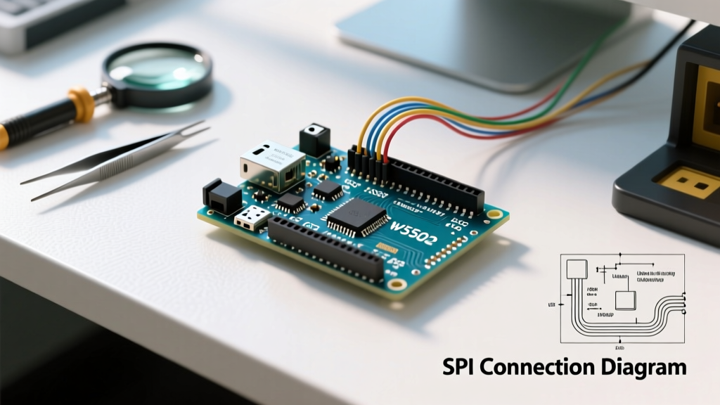
The W5500 communicates via the Serial Peripheral Interface (SPI) bus. Incorrect SPI routing is the number one cause of "Ethernet.begin() failed" errors. While shields plug directly into the ICSP header, breakout boards require manual wiring.
Arduino Uno / Nano (ATmega328P)
- MOSI: Pin 11
- MISO: Pin 12
- SCK: Pin 13
- SS (CS): Pin 10 (Must be hardware SS, even if you define a different pin in software)
- Reset: Pin 9 (Optional, but highly recommended for software-triggered PHY resets)
Arduino Mega 2560
The Mega routes SPI to different digital pins. If using a W5500 breakout board (not a stacked shield), you must wire to the following:
- MOSI: Pin 51
- MISO: Pin 50
- SCK: Pin 52
- SS (CS): Pin 53
Note: On both boards, the 6-pin ICSP header near the USB port also exposes MOSI, MISO, and SCK. Official Arduino Ethernet Shields V2 route SPI exclusively through the ICSP header to maintain Mega compatibility.
Software Configuration: DHCP and Static Fallback
To configure the software, use the official Arduino Ethernet Library. Ensure you have selected the correct chip in the library's initialization phase. Below is a robust configuration sketch that attempts a DHCP lease and falls back to a static IP if the DHCP server times out—a crucial pattern for remote industrial deployments.
#include <Ethernet.h>

// Assign a unique MAC address. Do not use the default in production.
byte mac[] = { 0xDE, 0xAD, 0xBE, 0xEF, 0xFE, 0xED };
IPAddress staticIP(192, 168, 1, 177);
IPAddress subnet(255, 255, 255, 0);
IPAddress gateway(192, 168, 1, 1);
IPAddress dns(8, 8, 8, 8);

EthernetServer server(80);

void setup() {
  Serial.begin(115200);

  // Disable SD card SPI to prevent bus collision (Crucial for shields)
  pinMode(4, OUTPUT);
  digitalWrite(4, HIGH);

  Serial.println("Initializing Ethernet...");

  // Attempt DHCP with a 5-second timeout
  if (Ethernet.begin(mac) == 0) {
    Serial.println("DHCP Failed. Configuring Static IP.");
    Ethernet.begin(mac, staticIP, dns, gateway, subnet);
  } else {
    Serial.print("DHCP Assigned IP: ");
    Serial.println(Ethernet.localIP());
  }

  // Check for hardware fault
  if (Ethernet.hardwareStatus() == EthernetNoHardware) {
    Serial.println("W5500 not found. Check SPI wiring.");
    while (true) { delay(1); }
  }

  server.begin();
}
Critical Edge Cases and Troubleshooting
When integrating Arduino and Ethernet hardware, theoretical circuit designs often meet real-world physical limitations. Here are the most common failure modes and their exact solutions.
1. The SD Card SPI Bus Collision
Most W5500 shields include a microSD card slot. Both the W5500 and the SD card share the same SPI bus (MOSI, MISO, SCK) but use different Chip Select (CS) pins. The W5500 uses Pin 10, while the SD card uses Pin 4.
The Fix: If you are not using the SD card, you must explicitly configure Pin 4 as an OUTPUT and set it HIGH in your setup() function. If left floating, the SD card controller may wake up and corrupt the SPI data lines, causing the W5500 to fail initialization.
2. Missing Auto-MDIX on Clone Boards
Modern network switches feature Auto-MDIX, automatically detecting and configuring crossover connections. However, many budget W5500 breakout boards sourced from overseas manufacturers omit the Auto-MDIX circuitry to save $0.40 per unit on the BOM (Bill of Materials).
The Symptom: The Arduino links successfully to a router/switch, but fails to ping when connected directly to a PC's Ethernet port via a standard Cat6 patch cable.
The Fix: Use a dedicated Ethernet Crossover Cable (T568B to T568A wiring) when connecting directly to a legacy PC NIC, or ensure you are routing through a managed switch that handles the MDIX translation.
3. PHY Initialization Timing and Reset Delays
The W5500 datasheet, available via the WIZnet W5500 official product page, specifies a strict power-on reset sequence. When the Arduino powers up, the 3.3V LDO on the Ethernet shield may take up to 150ms to stabilize. If the ATmega328P begins SPI polling before the W5500's internal PLL locks, the chip will enter a fault state.
The Fix: Always include a delay(200); immediately after powering on and before calling Ethernet.begin(). If your shield features a dedicated hardware reset pin connected to the Arduino, pulse it LOW for 50ms, then HIGH, followed by a 150ms delay before SPI initialization.
4. MAC Address Collisions in Fleet Deployments
Every Ethernet device requires a globally unique 48-bit MAC address. The official Arduino Ethernet Shield V2 comes with a pre-programmed EEPROM sticker containing a valid, registered MAC address. Clone boards do not.
If you deploy multiple Arduinos using the default 0xDE, 0xAD, 0xBE, 0xEF, 0xFE, 0xED array, your router's ARP table will experience constant thrashing, resulting in intermittent packet drops across all devices.
The Fix: Generate unique MAC addresses for every node. You can purchase blocks of EUI-48 identifiers from the IEEE Registration Authority, or use a locally administered MAC address scheme (setting the second least significant bit of the first byte to 1, e.g., 0x02) combined with a unique serial number derived from the ATmega's internal signature row.
Summary
Configuring an Arduino and Ethernet connection via the W5500 provides unmatched reliability for wired IoT nodes. By respecting SPI bus contention rules, implementing DHCP fallback logic, and accounting for physical layer quirks like Auto-MDIX and PHY reset timing, you can build networked microcontroller systems that operate flawlessly in demanding 24/7 environments.