
Why You Cannot Connect a Motor Directly to an Arduino
Attempting to drive a motor with Arduino by wiring it directly to the GPIO pins is a classic beginner mistake that will permanently destroy your microcontroller. The ATmega328P (found on the Arduino Uno R3) and the Renesas RA4M1 (found on the modern Arduino Uno R4 Minima) have a strict DC current limit per I/O pin of 20mA, with an absolute maximum rating of 40mA. Even a tiny 130-size hobby DC motor requires 150mA to run freely and can spike to 1.5A or more during a stall condition.
To safely control a motor, you must use an intermediary power stage. In this tutorial, we will explore how to drive a DC motor with Arduino using the ubiquitous L298N Dual H-Bridge module. We will cover the exact wiring, power supply requirements, PWM speed control, and the thermal realities of bipolar transistor motor drivers in 2026.
Bill of Materials (BOM) & Component Selection
Before wiring, ensure you have the correct components. Prices reflect average maker-market rates as of early 2026.
| Component | Specific Model / Spec | Est. Price | Engineering Notes |
|---|---|---|---|
| Microcontroller | Arduino Uno R3 or R4 Minima | $27.00 - $28.00 | R4 offers 48MHz processing but 5V logic remains identical for this use case. |
| Motor Driver | L298N Dual H-Bridge Module | $6.00 - $9.00 | Based on STMicroelectronics BJT Darlington array. High voltage drop (~2V). |
| DC Motor | 130-size or 775 DC Gear Motor | $4.00 - $15.00 | Ensure operating voltage is between 5V and 12V for this specific setup. |
| Power Supply | 2S 18650 Li-Ion Battery Holder | $4.00 | Provides 7.4V nominal (8.4V fully charged). Capable of 10A+ continuous discharge. |
| Alternative Driver | TB6612FNG Breakout | $4.50 | MOSFET-based. Much lower voltage drop (0.5V) and higher efficiency than L298N. |
The Power Supply Trap: Why 9V PP3 Batteries Fail
Many tutorials suggest using a standard 9V alkaline (PP3) battery to power the L298N and motor. Do not do this. A standard 9V alkaline battery has a very high internal resistance and is designed for low-drain applications like smoke detectors (drawing ~50mA). When your motor demands 500mA on startup, the battery voltage will instantly sag below the L298N's logic threshold, causing the Arduino to brown out and reset continuously. Always use a 2S Lithium-Ion (18650) pack or a high-current 5V/12V bench supply.
Understanding the H-Bridge and Voltage Drop
An H-Bridge allows you to reverse the polarity of the voltage applied to the motor, thereby changing its direction. The L298N achieves this using Bipolar Junction Transistors (BJTs) configured in a Darlington pair. While robust and forgiving of minor wiring errors, BJTs introduce a significant saturation voltage drop (Vce_sat).
According to the STMicroelectronics L298N Datasheet, the typical voltage drop across the driver is between 1.8V and 3.2V depending on the current draw. This means if you supply 9V to the L298N's VCC, your motor will only receive roughly 6.5V to 7V. If you are building a battery-operated robot where every volt of headroom matters, you should bypass the L298N and use a MOSFET-based driver like the TB6612FNG, which drops less than 0.5V.
Step-by-Step Wiring Guide
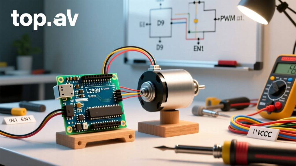
Follow this exact pinout to wire the Arduino, L298N, and power supply.
CRITICAL WARNING: You must establish a Common Ground. The ground of the battery pack, the ground of the L298N, and the GND pin of the Arduino MUST all be connected together. Without a common ground, the Arduino's 5V PWM logic signals have no reference voltage, and the motor will not respond.
- Power Supply to L298N: Connect the positive terminal of your 2S 18650 battery pack to the
12Vscrew terminal on the L298N. Connect the negative terminal to theGNDscrew terminal. - Common Ground: Run a jumper wire from the
GNDscrew terminal on the L298N to anyGNDpin on the Arduino. - Logic Power (5V): If your battery voltage is under 12V, leave the 5V-EN jumper cap ON the L298N. You can optionally wire the L298N's
5Voutput pin to the Arduino's5VorVINpin to power the board, though USB power is safer for initial testing. - Direction Control (IN1 & IN2): Connect L298N
IN1to Arduino Digital Pin8. Connect L298NIN2to Arduino Digital Pin7. - Speed Control (ENA): Remove the jumper cap from the
ENApins. Connect the exposedENApin to Arduino Digital Pin9(which supports hardware PWM via analogWrite()). - Motor Output: Connect your DC motor wires to the
OUT1andOUT2screw terminals. Polarity does not matter here; direction is handled in software.
Arduino C++ Code for PWM Speed and Direction Control
The following sketch encapsulates the motor logic into a reusable function. It accelerates the motor forward, stops, reverses, and then brakes.
// Pin Definitions
const int enA = 9;   // PWM Speed Control
const int in1 = 8;   // Direction 1
const int in2 = 7;   // Direction 2

void setup() {
  pinMode(enA, OUTPUT);
  pinMode(in1, OUTPUT);
  pinMode(in2, OUTPUT);

  // Ensure motor is off at startup
  digitalWrite(in1, LOW);
  digitalWrite(in2, LOW);
}

// Function to drive motor: speed (0-255), reverse (boolean)
void driveMotor(int speed, boolean reverse) {
  // Clamp speed to valid PWM range
  speed = constrain(speed, 0, 255);

  // Set direction
  digitalWrite(in1, reverse ? LOW : HIGH);
  digitalWrite(in2, reverse ? HIGH : LOW);

  // Apply PWM to Enable pin
  analogWrite(enA, speed);
}

void loop() {
  // Accelerate Forward
  for (int i = 0; i <= 255; i += 5) {
    driveMotor(i, false);
    delay(50);
  }

  // Coast for 1 second
  driveMotor(0, false);
  delay(1000);

  // Accelerate in Reverse
  for (int i = 0; i <= 255; i += 5) {
    driveMotor(i, true);
    delay(50);
  }

  // Hard Brake (Shorting motor terminals via L298N)
  digitalWrite(in1, HIGH);
  digitalWrite(in2, HIGH);
  analogWrite(enA, 255);
  delay(2000);
}
Common Failure Modes and Troubleshooting
When learning how to drive a motor with Arduino, you will inevitably encounter edge cases. Here is how to diagnose the most frequent hardware and software failures.
1. The Motor Whines but Will Not Spin
Cause: Insufficient stall current or PWM frequency mismatch. If the PWM value is too low (e.g., analogWrite(enA, 50)), the voltage may not be high enough to overcome the motor's static friction and internal magnetic cogging. The motor coils will vibrate (whine) at the Arduino's default Timer 1 PWM frequency (~490Hz), but the shaft won't turn.
Fix: Implement a "kickstart" routine in your code. Apply 255 (full power) for 50 milliseconds to break static friction, then immediately drop down to your desired lower PWM cruising speed.
2. The L298N Module is Extremely Hot to the Touch
Cause: Thermal dissipation limits of the Darlington BJT array. If you are pulling 1.5A through the L298N with a 2V voltage drop, the chip is dissipating 3 Watts of pure heat (P = V × I). The stock aluminum heatsink on cheap clone modules is rarely sufficient for continuous operation above 1A.
Fix: If your application requires continuous current above 1A, abandon the L298N. Upgrade to a modern MOSFET driver like the Texas Instruments DRV8871 or the Toshiba TB6612FNG, which operate with minimal thermal loss.
3. Arduino Resets Randomly When Motor Stops or Reverses
Cause: Back-Electromotive Force (Back-EMF) and Ground Bounce. When a spinning motor is suddenly powered off or reversed, its inductance generates a massive reverse voltage spike. While genuine L298N modules include built-in 1N4007 flyback diodes to route this spike back to the power supply, cheap clones often omit them or use undersized diodes. Furthermore, high current surges through thin ground wires can cause the ground reference to "bounce," resetting the Arduino's brown-out detector (BOD).
Fix: Solder external Schottky flyback diodes across the motor terminals if using a clone board. Ensure your ground wires are thick (18 AWG or lower) and keep the motor power wiring physically separated from the Arduino's sensitive logic wiring.