
The Pitfalls of Ad-Hoc Temperature Control
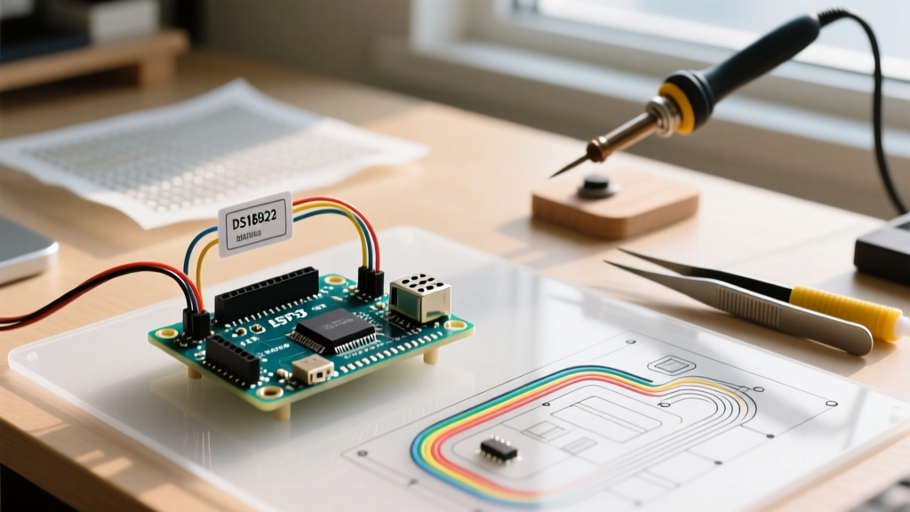
Building an Arduino temperature controller often devolves into a frustrating cycle of relay chatter, severe overshoot, and thermal instability. Most makers begin by wiring a DS18B20 sensor to a 5V mechanical relay, writing a simple if (temp < target) digitalWrite(RELAY, HIGH) script, and wondering why their system oscillates wildly. This ad-hoc approach ignores thermal mass, sensor latency, and derivative control. By shifting to a structured engineering workflow, you can eliminate guesswork, reduce component wear, and achieve laboratory-grade stability (±0.1°C) for under $45 in components.
Phase 1: Hardware Selection and Thermal Mass Matching
The most common workflow bottleneck occurs when developers select hardware without considering the thermal mass of their target environment. A 3D printer hotend (low mass, fast response) requires entirely different hardware than a 20-liter sous-vide water bath (high mass, slow response).
Sensor Selection Matrix
| Sensor Type | Typical Cost | Response Time | Accuracy | Best Application |
|---|---|---|---|---|
| DS18B20 (1-Wire) | $3 - $5 | 750ms (12-bit) | ±0.5°C | Slow ambient/liquid monitoring |
| PT100 RTD + MAX31865 | $18 - $24 | <100ms | ±0.1°C | Precision industrial, 3D printing |
| Type K + MAX6675 | $12 - $16 | <200ms | ±2.0°C | High-temp kilns, reflow ovens |
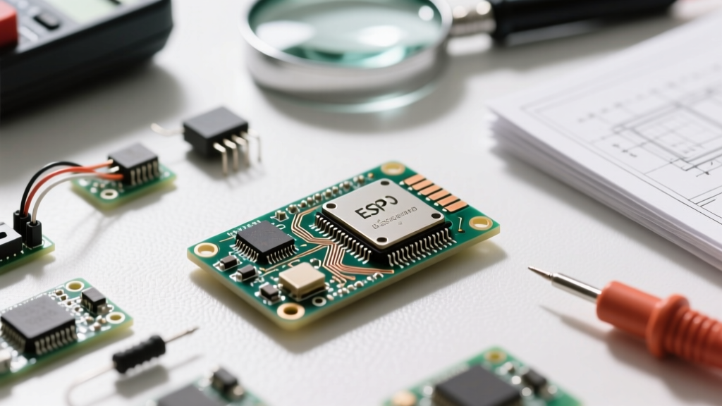
For precision workflows under 300°C, the PT100 RTD paired with Adafruit's MAX31865 breakout board is the undisputed standard. For actuation, abandon mechanical relays. A mechanical relay switching a 1000W AC heater will fail within weeks due to arcing and contact welding. Instead, specify a Zero-Crossing Solid State Relay (SSR) like the Omron G3NA-210B (~$22) or Crydom D2425 (~$35). Zero-crossing SSRs minimize inrush current and drastically reduce Electromagnetic Interference (EMI).
Phase 2: Sensor Calibration and Linearization
Raw ADC readings are useless for precision control. Your workflow must include a mandatory calibration step. For thermistors, implement the Steinhart-Hart equation rather than relying on the Beta parameter equation, which loses accuracy outside a narrow 25°C band.
For RTDs, the MAX31865 handles linearization internally, but you must configure the correct reference resistor (typically 430Ω for PT100, 4300Ω for PT1000). To validate your sensor, perform a 3-point calibration against a NIST-traceable reference. Use an ice-water slurry (0.00°C), a calibrated dry-block calibrator at your setpoint, and boiling water adjusted for your exact barometric pressure. According to NIST thermometry guidelines, mapping these offsets in an EEPROM lookup table eliminates systemic drift before the control loop even begins.
Phase 3: PID Tuning Strategy
Proportional-Integral-Derivative (PID) control is mandatory for stable temperature regulation. However, blindly guessing Kp, Ki, and Kd values wastes hours. Integrate the Ziegler-Nichols tuning method into your workflow to mathematically derive your constants.
The Ziegler-Nichols Workflow
- Disable I and D: Set Ki and Kd to zero. Start with a low Kp.
- Induce Oscillation: Gradually increase Kp until the system exhibits sustained, uniform oscillations. This is your Ultimate Gain (Ku).
- Measure the Period: Record the time between oscillation peaks in seconds. This is your Ultimate Period (Tu).
- Calculate Constants: Use the standard Ziegler-Nichols formulas: Kp = 0.6 * Ku, Ki = 2 * Kp / Tu, Kd = Kp * Tu / 8.
For a faster workflow, utilize Brett Beauregard's Arduino PID AutoTune library, which automates the relay-switching logic required to find Ku and Tu. As detailed in the University of Michigan Control Tutorials, derivative action (Kd) is highly sensitive to sensor noise; if your PT100 readings fluctuate by more than 0.2°C per sample, apply a 5-sample moving average filter before feeding the data into the derivative calculation.
Phase 4: Non-Blocking Code Architecture
A critical failure point in maker-built controllers is the use of delay() functions. Temperature control loops require strict, deterministic timing (typically 10Hz to 50Hz). If your code blocks to update an LCD display or read a serial command, the PID algorithm receives irregular time-step (dt) inputs, causing the integral and derivative terms to miscalculate and destabilize the system.
Implement a finite state machine using millis() to separate your control loop from your UI loop. The PID computation should run every 100ms, while the I2C OLED display updates every 500ms. This decoupling ensures the math remains pristine regardless of UI latency.
When using the standard Arduino PID library, ensure you call myPID.SetMode(AUTOMATIC) only when the system is actively controlling, and switch to MANUAL during safety faults. Furthermore, use myPID.SetOutputLimits(0, 255) to map the PID output directly to an 8-bit PWM signal driving the SSR. This prevents integral windup—a scenario where the integral term accumulates massive error during saturation, causing severe overshoot when the system finally approaches the setpoint.
Edge Cases: EMI, Heatsinking, and Thermal Runaway
Even with perfect code, hardware edge cases will derail your project if ignored. Switching high-wattage AC loads via SSRs generates massive EMI spikes, which can couple into the ATmega328P's power rails, causing brownout resets and leaving your heater permanently ON.
Pro-Tip: The Snubber Circuit
Always wire an RC snubber network (a 100Ω carbon composition resistor in series with a 0.1µF X2-rated capacitor) directly across the SSR's AC output terminals. This suppresses the voltage spike caused by inductive loads and protects your microcontroller from fatal EMI resets.
SSR heatsinking is another frequently overlooked workflow step. An SSR like the Omron G3NA-210B will dissipate roughly 1.2V across its internal triac. At a 10A load, that equals 12W of heat. Without a proper aluminum heatsink and a thin layer of thermal interface material (TIM), the SSR will thermally throttle or fail catastrophically within minutes. Calculate your expected continuous current, multiply by 1.2V, and select a heatsink with a thermal resistance (°C/W) low enough to keep the SSR casing below 80°C in your ambient environment.
Finally, implement a hardware-level thermal runaway watchdog. Use a secondary, independent analog thermistor tied to a hardware comparator (like the LM393) that physically cuts the SSR's DC control voltage if the temperature exceeds the setpoint by 15°C. Software can crash; hardware comparators do not. By integrating these defensive engineering steps into your standard workflow, your Arduino temperature controller will transition from a fragile prototype to a robust, deployable instrument.