
The Architecture Divide: How Different MCUs Handle Interrupts
When makers transition from a classic Arduino Uno to modern platforms like the ESP32-S3 or Raspberry Pi RP2040, they often assume that attachInterrupt() behaves identically across all boards. This assumption is the root cause of countless phantom triggers, hard locks, and timing drifts. The reality is that 'interrupts Arduino' compatibility is an abstraction layered over wildly different silicon architectures.
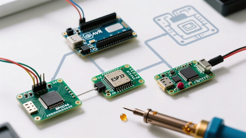
While the Arduino IDE abstracts the setup via digitalPinToInterrupt(pin), the underlying hardware routing, memory constraints, and pin limitations dictate whether your Interrupt Service Routine (ISR) will execute reliably. This guide breaks down the hardware realities of AVR, ESP32, and RP2040 architectures, providing a definitive compatibility matrix and troubleshooting framework for cross-platform embedded development.
AVR (ATmega328P / ATmega2560): Hardware vs. Pin Change Interrupts
The classic 8-bit AVR architecture splits interrupts into two distinct categories: dedicated Hardware Interrupts (INT) and Pin Change Interrupts (PCINT).
Dedicated Hardware Interrupts (INT)
On the ATmega328P (Uno/Nano), only digital pins D2 and D3 support dedicated hardware interrupts (INT0 and INT1). These pins are tied to specific interrupt vectors that can trigger on LOW, CHANGE, RISING, or FALLING edges. The ATmega2560 (Mega 2560) expands this to six dedicated pins (D2, D3, D18, D19, D20, D21). Because these are handled by the External Interrupt Control Registers (EICRA/EICRB), they offer the lowest latency and highest reliability for time-critical tasks like quadrature encoders.
Pin Change Interrupts (PCINT)
If you need to trigger an ISR on an analog pin or a non-INT digital pin on an AVR, you must use Pin Change Interrupts. Unlike INT pins, PCINTs only trigger on a CHANGE state (they cannot natively distinguish between RISING and FALLING without software polling inside the ISR). Furthermore, PCINTs are grouped by hardware ports (PCMSK0, PCMSK1, PCMSK2). If you enable a PCINT on pin D8 (Port B), the ISR will fire for any state change on pins D8 through D13. You must manually read the port register inside the ISR to determine which specific pin triggered the event.
Expert Insight: For AVR PCINT management, avoid writing raw register masks unless necessary. The community-maintained EnableInterrupt library handles the port-level masking and software debouncing far more reliably than manual
PCICRmanipulation, saving hours of debugging phantom triggers.
ESP32 & ESP32-S3: GPIO Matrix and IRAM Constraints
The 32-bit Xtensa (and RISC-V in the C-series) architecture of the ESP32 family utilizes a highly flexible GPIO Matrix. This allows almost any peripheral signal, including interrupts, to be routed to almost any GPIO pin. However, this flexibility introduces severe hardware-specific compatibility traps.
The Input-Only Pin Trap (GPIO 34-39)
On the original ESP32, GPIOs 34 through 39 are strictly input-only. Crucially, they lack internal pull-up and pull-down resistors. If you attach an interrupt to GPIO 34 for a mechanical switch or an open-drain sensor without providing an external 10kΩ pull-up resistor, the pin will float. Electromagnetic noise will trigger the ISR hundreds of times per second, starving the main loop and potentially triggering the ESP32's Task Watchdog Timer (WDT) reset.
IRAM Execution Requirements
When the ESP32 reads from or writes to its external SPI Flash, it temporarily disables the cache. If an interrupt fires during this exact microsecond, and the ISR code resides in standard flash memory, the CPU will crash with a Guru Meditation Error: Core panic'ed (Cache disabled but cached memory region accessed). To prevent this, critical ISRs must be placed in Instruction RAM (IRAM) using the IRAM_ATTR macro. According to the Espressif Interrupt Allocator documentation, ISRs handling high-frequency events or flash-heavy operations must be explicitly flagged for IRAM allocation to ensure zero-latency execution.
RP2040: Shared IRQ Banks and PIO Integration
The Raspberry Pi RP2040 (used in the Pico) features 30 GPIO pins, but it does not map each pin to a unique interrupt vector. Instead, all GPIO pins share just four bank-level interrupt channels (IO_IRQ_BANK0). The Arduino core for the RP2040 abstracts this beautifully via attachInterrupt(), mapping your specific pin to the shared handler.
However, compatibility issues arise when mixing the Arduino IDE with the native Pico SDK. If your sketch utilizes the Programmable I/O (PIO) state machines alongside standard GPIO interrupts, you must ensure that the PIO interrupt vectors (PIO0_IRQ_0, PIO1_IRQ_0) do not conflict with the Arduino core's bank-level IRQ routing. Always clear the interrupt flag explicitly in the RP2040 ISR using gpio_acknowledge_irq(pin, event) to prevent infinite ISR looping.
Cross-Platform Pin Mapping & Compatibility Matrix
Use the following matrix to determine hardware limits before designing your PCB or breadboard layout. This data reflects the standard Arduino core implementations as of 2026.
| MCU / Board | Dedicated INT Pins | PCINT / Shared Support | Max Simultaneous ISRs | Internal Pull-Up Limitations |
|---|---|---|---|---|
| ATmega328P (Uno/Nano) | 2 (D2, D3) | Yes (Grouped by Port) | ~20 (Memory bound) | None (All digital pins have pull-ups) |
| ATmega2560 (Mega) | 6 (D2, D3, D18-D21) | Yes (Grouped by Port) | ~40 (Memory bound) | None |
| ESP32 (Original) | 34 (Via GPIO Matrix) | N/A (Matrix routed) | 64 (Hardware channels) | GPIO 34-39 lack internal pull-ups |
| ESP32-S3 | 45 (Via GPIO Matrix) | N/A (Matrix routed) | 64 (Hardware channels) | GPIO 0-21 (Strapping pins require care) |
| RP2040 (Pico) | 30 (Shared Bank IRQs) | N/A (Bank routed) | 4 Bank Channels | None (All GPIOs support pull-ups) |
Fatal ISR Failure Modes & Edge Cases
Writing an ISR that compiles is easy; writing one that doesn't corrupt your system state requires understanding the following failure modes.
1. The I2C / SPI Deadlock
Never call Wire.requestFrom() or SPI.transfer() inside an ISR. The Arduino Wire library relies on its own background interrupts to handle clock stretching and ACK/NACK polling. If your hardware ISR fires and blocks the global interrupt flag (which AVRs do automatically upon entering an ISR), the I2C interrupt will never fire, causing the Wire library to hang indefinitely. Solution: Set a volatile boolean flag inside the ISR, and handle the I2C transaction in the loop().
2. Timer0 Drift and millis() Freeze
On AVR boards, the millis() and delay() functions rely on the Timer0 overflow interrupt. If your custom ISR takes longer than 1ms to execute, or if you use noInterrupts() for extended periods, Timer0 overflows will be missed. This results in severe timing drift. As noted in the official Arduino attachInterrupt() reference, ISRs should be as short as possible—ideally executing in under 50µs.
3. Volatile Keyword Misuse
Variables shared between the ISR and the main loop must be declared volatile. However, on 32-bit architectures (ESP32, RP2040), reading or writing a 32-bit integer is generally atomic. On 8-bit AVRs, reading a 32-bit long takes multiple clock cycles. If an ISR modifies a 32-bit counter exactly while the main loop is reading it, the main loop will read a corrupted, hybrid value. Solution: Wrap multi-byte variable reads in the main loop with noInterrupts() and interrupts().
Best Practices for Cross-Platform ISR Development
To ensure your code remains compatible whether you are flashing an ancient Uno or a modern ESP32-S3, adhere to these architectural rules:
- Use digitalPinToInterrupt(): Never hardcode interrupt numbers (e.g.,
attachInterrupt(0, ...)). Always useattachInterrupt(digitalPinToInterrupt(pin), ...)to let the core map the physical pin to the correct hardware vector. - Hardware Debouncing for Mechanical Switches: Software debouncing inside an ISR (using
millis()) is unreliable across platforms due to execution context limits. Use a simple hardware RC filter (10kΩ resistor + 0.1µF capacitor) or a dedicated Schmitt trigger IC like the 74HC14 to clean the signal before it hits the GPIO. - Avoid Serial.print() in ISRs: The
Serialobject uses hardware UART buffers that rely on background interrupts to shift data out. CallingSerial.print()inside an ISR will cause a deadlock on AVR and unpredictable latency on ESP32. - Consult the Datasheet for Strapping Pins: On the ESP32-S3, GPIO 0, 3, 45, and 46 are strapping pins read during boot. Attaching interrupts to these pins with external pull-downs can prevent the MCU from entering normal flash execution mode upon reset.
Understanding the silicon beneath the Arduino abstraction layer is what separates a fragile prototype from a production-ready embedded system. By respecting the unique interrupt routing, memory constraints, and pin limitations of your target MCU, you can harness the full, deterministic power of hardware interrupts.
For deeper insights into AVR-specific interrupt vector tables and macro definitions, refer to the avr-libc ISR documentation.