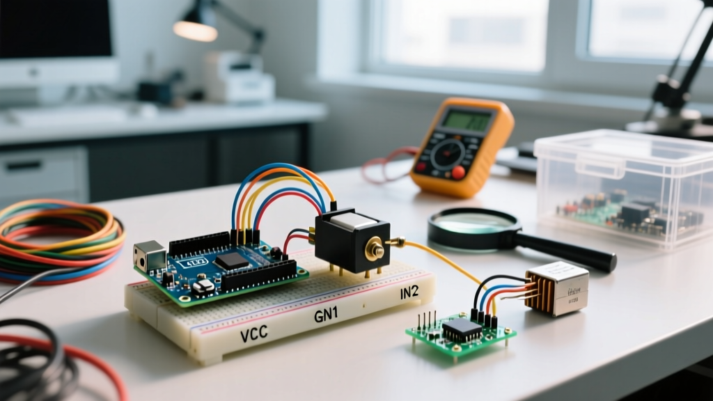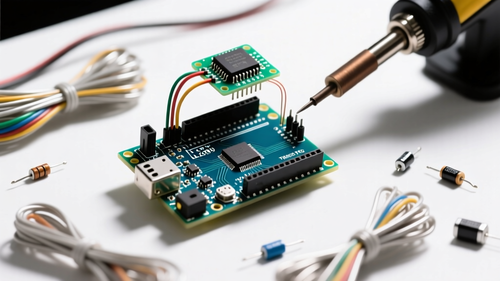

The Fundamental Rule: Why Arduino Cannot Drive Motors Directly
When transitioning from blinking LEDs to building mobile robots or automated actuators, every maker encounters the same hardware limitation: microcontrollers are designed for logic, not power. The ATmega328P chip at the heart of the classic Arduino Uno has an absolute maximum DC current limit of 40mA per GPIO pin, with a recommended operating current of just 20mA. According to the Arduino Official Digital Pins Documentation, exceeding this limit will permanently damage the silicon die, effectively bricking the microcontroller.
A standard 130-size DC hobby motor, commonly used in beginner robotics, draws between 300mA and 800mA under load, with startup inrush currents frequently exceeding 1.5A. Connecting this directly to an Arduino pin will instantly destroy the output driver. This is exactly why an Arduino motor controller is mandatory. The motor controller acts as a high-current muscle, taking low-power logic signals (3.3V or 5V at a few milliamps) from the Arduino and switching a separate, high-current power supply to drive the motor.
Demystifying the H-Bridge Topology
At the core of almost every bidirectional DC motor controller is a circuit topology known as the H-bridge. Named for its schematic resemblance to the letter 'H', this circuit utilizes four independent switches (typically MOSFETs or BJTs) arranged around the motor.
By selectively closing specific pairs of switches, you control both the direction and the state of the motor. Here is the logic matrix for a standard H-bridge:
| Switch 1 (High-Side Left) | Switch 2 (Low-Side Left) | Switch 3 (High-Side Right) | Switch 4 (Low-Side Right) | Motor State |
|---|---|---|---|---|
| CLOSED | OPEN | OPEN | CLOSED | Forward |
| OPEN | CLOSED | CLOSED | OPEN | Reverse |
| OPEN | CLOSED | OPEN | CLOSED | Dynamic Braking |
| OPEN | OPEN | OPEN | OPEN | Coasting (Freewheeling) |
The Danger of Shoot-Through
If Switch 1 and Switch 2 are closed simultaneously, you create a direct short circuit from the power supply to ground. This catastrophic failure mode is called 'shoot-through' and will instantly vaporize the silicon inside the motor driver IC. Modern Arduino motor controller modules prevent this by integrating 'dead-time' logic and interlocking hardware gates, ensuring that a high-side and low-side switch on the same leg can never be active at the exact same microsecond.
Pulse Width Modulation (PWM) for Speed Control
While the H-bridge handles direction, speed is controlled via Pulse Width Modulation (PWM). Instead of lowering the voltage (which is inefficient and causes torque loss), the Arduino rapidly toggles the power to the motor on and off. Because the motor's armature has physical inertia and electrical inductance, it averages these rapid pulses into a smooth rotational speed.
The Arduino Uno generates hardware PWM signals at two default frequencies: approximately 490Hz on pins 5, 6, 9, 10, and 11, and 980Hz on pin 3. A 25% duty cycle means the power is ON for 25% of the pulse period and OFF for 75%. For most DC motors, 490Hz is sufficient, but if your project involves audio-sensitive environments or high-end precision robotics, you may need to reconfigure the Arduino's internal timers to push the PWM frequency above the audible 20kHz range to eliminate high-pitched motor whine.
2026 Motor Controller IC Comparison Matrix
The market for motor driver ICs has evolved significantly. While legacy chips are still widely available, modern MOSFET-based drivers offer vastly superior efficiency. Below is a technical comparison of the most common ICs used in Arduino motor controller modules available in 2026.
| IC Model | Topology | Continuous Current | Logic Voltage Drop | Typical 2026 Module Price | Best Use Case |
|---|---|---|---|---|---|
| L298N | BJT (Bipolar) | 2.0A per channel | ~2.0V to 2.5V | $3.50 - $5.00 | Legacy education kits, high-voltage (24V) low-efficiency builds. |
| TB6612FNG | MOSFET | 1.2A per channel | ~0.5V | $6.50 - $9.00 | Efficient mobile robots, battery-powered rovers, 3D printer extruders. |
| DRV8871 | MOSFET | 3.6A (Single Channel) | ~0.4V | $4.00 - $7.00 | Single high-torque DC motors, linear actuators, automated winches. |
| BTS7960 | MOSFET (Half-Bridge) | 20A+ (Continuous) | Very Low | $15.00 - $25.00 | Heavy combat robotics, large wheelchair motors, high-amperage 12V/24V systems. |
As noted in the Texas Instruments Motor Driver Portfolio, the shift from BJT to MOSFET topologies in low-voltage applications is driven by the need to minimize thermal dissipation. The L298N wastes up to 4 watts of power as heat at 2A, requiring a bulky aluminum heatsink. The TB6612FNG, utilizing advanced MOSFETs, dissipates a fraction of that heat, allowing for much smaller breakout boards. For detailed specifications on highly efficient dual-channel drivers, the Pololu TB6612FNG Dual Motor Driver Breakout documentation remains an industry-standard reference for integration and thermal limits.
Real-World Failure Modes and Edge Cases
Even with the correct Arduino motor controller, makers frequently encounter system instability. Understanding these failure modes is the difference between a working prototype and a frustrating debugging session.
1. The Brownout Reset Dance
When a DC motor starts, it draws a massive inrush current (stall current). If your motor power supply and Arduino logic share the same voltage regulator, this current spike will cause the voltage rail to sag. The ATmega328P features a Brown-out Detection (BOD) circuit that automatically resets the microcontroller if the voltage drops below 4.3V (on a 5V board) or 2.7V (on a 3.3V board). This results in the Arduino endlessly rebooting every time the motor attempts to spin. Solution: Always use a dedicated power supply for the motors, or ensure your main BEC (Battery Eliminator Circuit) can supply at least 3A of continuous current with low transient voltage drop.
2. Back-EMF Voltage Spikes
Motors are inductive loads. When you abruptly cut power to a spinning motor, the collapsing magnetic field induces a massive reverse voltage spike (Back-Electromotive Force). If unmanaged, this spike can exceed the breakdown voltage of the motor controller's MOSFETs, punching through the silicon and permanently shorting the driver. Modern modules include flyback diodes (usually 1N5819 Schottky diodes) to safely route this spike back into the power loop. If you are designing a custom PCB rather than using a pre-built module, you must manually place these diodes in parallel with the motor terminals.
3. Ground Loop and Logic Translation Errors
A surprisingly common mistake is forgetting to connect the ground of the motor power supply to the ground of the Arduino. The motor controller needs a shared reference point to accurately read the 5V logic HIGH signal from the Arduino GPIO. Without a common ground, the logic signals 'float,' resulting in erratic motor twitching or complete failure to respond.
Professional Wiring and Decoupling Strategies
To ensure robust operation in electrically noisy environments, implement the following hardware-level best practices:
- Star Grounding: Route the ground from the battery, the motor controller, and the Arduino to a single, central physical point. Do not daisy-chain grounds through breadboard rails, as the resistance of breadboard clips can introduce ground bounce.
- Decoupling Capacitors: Solder a 100nF ceramic capacitor directly across the motor terminals to suppress high-frequency brush noise. Additionally, place a large electrolytic capacitor (100µF to 470µF) across the main power input terminals of the motor controller to act as a local energy reservoir during inrush current events.
- Twisted Pair Wiring: When routing high-current wires from the motor controller to the motor, twist the positive and negative cables together. This minimizes the loop area, drastically reducing the electromagnetic interference (EMI) radiated into nearby Arduino sensor wires, such as I2C or SPI communication lines.
Expert Insight: If you are using an Arduino Mega or ESP32 alongside high-current motor controllers, keep your I2C sensor cables (like LiDAR or IMUs) physically separated from motor power wires by at least 2 inches. High dI/dt (change in current over time) from PWM switching can induce phantom voltages in adjacent unshielded signal wires, causing I2C bus lockups.
Summary
Selecting and implementing the right Arduino motor controller requires moving beyond simple plug-and-play assumptions. By understanding the physics of the H-bridge, the nuances of PWM frequency, and the thermal realities of BJT versus MOSFET ICs, you can design robotic systems that are not only functional but electrically robust. Whether you choose the budget-friendly L298N for a simple school project or the high-efficiency TB6612FNG for a battery-constrained autonomous rover, respecting the electrical boundaries of your microcontroller will ensure your projects survive long past the prototyping phase.