
The Reality of Microcontroller Audio DSP in 2026
Building a custom arduino effects pedal is one of the most rewarding projects in the maker space, bridging the gap between analog circuit design and digital signal processing (DSP). However, the leap from blinking LEDs to processing real-time, high-fidelity audio is fraught with pitfalls. While early tutorials often suggest using an Arduino Uno for audio, the ATmega328P's 8-bit ADC and 16MHz clock yield a dismal 9kHz Nyquist limit and unacceptable signal-to-noise ratios.
In 2026, serious DIY pedal builders rely on 32-bit ARM Cortex-M7 boards like the Teensy 4.0/4.1 (priced around $32) or the Arduino Giga R1 WiFi, paired with dedicated I2S audio codecs like the SGTL5000 or PCM5102A. Even with this advanced hardware, builders frequently encounter 60Hz hum, harsh digital clipping, and latency-induced phase issues. This guide provides a deep-dive diagnostic framework to troubleshoot and resolve these critical audio path failures.
Core Diagnostic Matrix: Symptom to Solution
Before breaking out the oscilloscope, cross-reference your pedal's primary failure mode with this diagnostic matrix.
| Symptom | Probable Root Cause | Diagnostic Step | Hardware/Code Fix |
|---|---|---|---|
| 60Hz/120Hz Hum & Buzz | Ground loops or unfiltered switching PSU noise | Disconnect USB; run on battery. If hum stops, it is a ground loop. | Implement star grounding; use an isolated DC-DC converter (e.g., Murata NMH0509SC). |
| Harsh Digital Clipping | Guitar transient spikes exceeding ADC VREF (3.3V) | Probe the op-amp output with an oscilloscope while striking strings aggressively. | Add a soft-clipping BAT54 Schottky diode network; adjust input gain staging. |
| 'Tone Suck' (Loss of Highs) | Impedance mismatch between pickup and ADC | Measure AC impedance; check if high frequencies roll off above 3kHz. | Insert a high-input-impedance JFET/CMOS buffer (e.g., OPA2134 or TL072) before the ADC. |
| Metallic Artifacts / Aliasing | Missing or poorly tuned anti-aliasing filter | Feed a 25kHz sine wave into the input; check output spectrum for fold-back. | Design a 2nd-order Sallen-Key active low-pass filter with a cutoff at 20kHz. |
| Noticeable Latency (>15ms) | Oversized I2S buffer blocks or CPU overload | Monitor CPU usage via serial print; check for FFT/convolution spikes. | Reduce AudioMemory() allocation; optimize DSP math using ARM CMSIS libraries. |
Diagnosing the Analog Front-End: Clipping and Impedance
The most common reason an arduino effects pedal sounds like a 'fuzz' pedal even when bypassed is improper analog front-end design. Electric guitar pickups are high-impedance sources (typically 100kΩ to 300kΩ AC impedance). If you feed this directly into a microcontroller's ADC (which expects a source impedance under 10kΩ), the internal sampling capacitor cannot charge fully during the acquisition window, resulting in severe high-frequency attenuation and distortion.
The Buffer and Bias Stage
To solve this, you must buffer the signal. A dual op-amp like the OPA2134 (FET-input, ultra-low noise, ~$8) or the budget-friendly TL072 (~$1) is mandatory. Furthermore, because modern ARM microcontrollers operate on 3.3V logic, the ADC can only read positive voltages from 0V to 3.3V. Audio signals, however, are AC and swing positive and negative.
Pro-Tip: Never use a simple resistor voltage divider to create your 1.65V virtual ground without buffering it. When the op-amp draws current during transient peaks, an unbuffered voltage divider will sag, modulating your audio signal with low-frequency 'motorboating' noise. Use a dedicated rail-splitter IC like the TLE2426 or buffer the divider with the second half of your TL072.
Transient Clipping Protection
A hard pick attack on a bass string can generate transient voltage spikes exceeding 3V. If your op-amp is powered by a single 3.3V supply, it will hard-clip against the rail, sending harsh square waves into the ADC. To diagnose this, probe the op-amp output while striking the strings. If you see flat-topped waveforms, implement a soft-clipping network using BAT54 Schottky diodes wired from the signal line to the 3.3V rail and to ground. Schottky diodes have a lower forward voltage drop (~0.3V) compared to standard 1N4148 diodes, providing smoother saturation characteristics before the ADC maxes out.
Power Supply Rejection and Ground Loops
Audio noise in DIY pedals is rarely the microcontroller's fault; it is almost always a power delivery failure. Pedalboards are notoriously noisy environments, filled with daisy-chained switching power supplies that inject high-frequency switching noise and 60Hz/120Hz ripple into the ground plane.
Breaking the Ground Loop
If your pedal emits a loud hum that disappears when you touch the strings or the chassis, you have a ground loop. This occurs when the shield of the audio cable and the USB/power ground create a parallel path for stray currents. According to best practices outlined in the Analog Devices Guide on Grounding Data Converters, mixed-signal systems require strict separation of analog and digital ground planes, tied together at exactly one 'star' point—usually at the ADC's ground pin.
To completely eliminate PSU-induced noise in a live gigging environment, integrate an isolated 1W DC-DC converter (such as the Murata NMH0509SC or Traco Power TEL 10) into your power jack circuit. These modules use internal transformers to galvanically isolate the pedal's internal ground from the pedalboard's main power bus, physically breaking the loop.
Troubleshooting I2S Latency and DSP Bottlenecks
When using an I2S audio codec like the SGTL5000 (found on the Teensy Audio Shield) or the PCM5102A, audio data is transferred in blocks. The PJRC Teensy Audio Library Documentation defaults to a block size of 128 samples. At a 44.1kHz sample rate, 128 samples equate to roughly 2.9 milliseconds of latency per block.
The CPU Overload Trap
Total system latency includes ADC conversion, DSP processing, and DAC output. A basic overdrive algorithm might add only 1ms, resulting in an imperceptible 6ms total latency. However, if your arduino effects pedal uses heavy algorithms like convolution reverb or large FFTs (Fast Fourier Transforms), the CPU may fail to process the block before the next I2S interrupt fires. This causes buffer underruns, which manifest as metallic clicks, dropouts, or a robotic 'aliasing' sound.
How to diagnose and fix DSP latency:
- Monitor CPU Load: Use
AudioProcessorUsage()andAudioMemoryUsage()in your serial loop. If CPU usage spikes above 85%, you are risking underruns. - Optimize Memory Allocation: If
AudioMemoryUsage()frequently hits your allocated limit, increase yourAudioMemory(X)definition. However, allocating too much memory can cause cache thrashing on Cortex-M7 chips, ironically increasing latency. - Leverage Hardware Math: Replace standard C++
sin()andcos()functions with ARM CMSIS-DSP library equivalents (e.g.,arm_sin_f32()), which utilize the microcontroller's hardware Floating Point Unit (FPU) to execute math in single-cycle instructions.
Step-by-Step Oscilloscope Triage
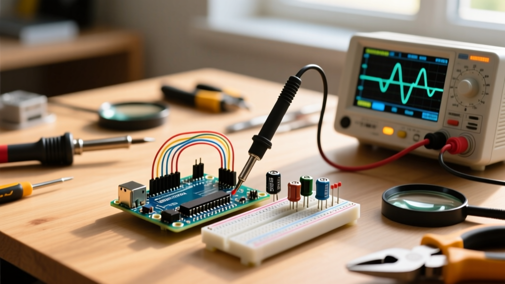
When the code compiles, the I2S locks, but the audio output is garbage, follow this strict signal-chain triage:
- Step 1: Probe the 3.3V Rail. Set your scope to AC coupling and 10mV/div. You should see a flat line. If you see >50mV of ripple, your voltage regulator is inadequate. Upgrade to a high-PSRR LDO like the LT1761.
- Step 2: Probe the Virtual Ground (1.65V). Strum the guitar aggressively. If the 1.65V line dips or spikes, your buffer op-amp is failing to source current. Decrease the voltage divider resistor values from 10kΩ to 2.2kΩ, or add a decoupling capacitor (10µF tantalum) to the virtual ground node.
- Step 3: Probe the I2S Lines. Check the BCLK (Bit Clock) and LRCLK (Left/Right Clock). If the clock jitter exceeds 2ns, the microcontroller's internal PLL is struggling. Ensure your PCB traces for I2S are kept short, equal-length, and routed away from switching power inductors.
Final Thoughts on Advanced DSP
Designing a professional-grade arduino effects pedal requires respecting both the laws of analog physics and the rigid timing constraints of digital interrupts. By properly buffering your high-impedance guitar signal, isolating your power delivery from noisy pedalboards, and optimizing your DSP block sizes, you can achieve studio-quality audio processing on a sub-$50 microcontroller footprint. For those looking to design advanced FIR and IIR filters for their custom EQ and cabinet impulse responses, the mathematical foundations detailed in Julius O. Smith's Stanford CCRMA Filter Design Resources remain the gold standard for translating analog filter topologies into efficient C++ code.