
Understanding the ADC on Arduino: The Shift to 14-Bit Precision
The Analog-to-Digital Converter (ADC) is the critical bridge between real-world physical phenomena and digital microcontroller logic. For years, the maker community relied on the classic Arduino Uno R3 and its ATmega328P microcontroller, which featured a modest 10-bit ADC. However, as of 2026, the standard for professional and advanced hobbyist prototyping has shifted to the Arduino Uno R4 Minima and WiFi models. Powered by the Renesas RA4M1 ARM Cortex-M4 processor, the R4 series introduces a native 14-bit Successive Approximation Register (SAR) ADC, fundamentally changing how we approach signal acquisition, noise management, and calibration when using the adc on arduino.
According to the official Arduino Uno R4 hardware documentation, the RA4M1's ADC offers significantly higher granularity, but this increased resolution also makes the circuit far more susceptible to electromagnetic interference (EMI) and source impedance mismatches. This tutorial provides a comprehensive, engineer-level guide to wiring, coding, and calibrating the ADC on modern Arduino boards.
Hardware Resolution Comparison Matrix
Before writing a single line of code, it is vital to understand the mathematical reality of your microcontroller's ADC. The voltage step size—often called the Least Significant Bit (LSB) weight—dictates your theoretical measurement precision.
| Microcontroller Board | Core Architecture | ADC Resolution | Discrete Steps | Voltage Step (at 5V VREF) |
|---|---|---|---|---|
| Arduino Uno R3 (Legacy) | ATmega328P (8-bit AVR) | 10-bit | 1,024 | 4.88 mV |
| Arduino Uno R4 Minima | Renesas RA4M1 (ARM M4) | 14-bit | 16,384 | 0.305 mV |
| ESP32-S3 DevKit | Xtensa LX7 (Dual-core) | 12-bit | 4,096 | 0.805 mV (at 3.3V VREF) |
With the Uno R4, a 5V reference yields a step size of just 0.305 mV. While this allows for highly precise sensor readings (such as detecting minute strain gauge deflections or precise thermistor variations), it also means that even 1 mV of power rail noise will cause the lowest 3 bits to fluctuate wildly.
Step-by-Step Wiring for Signal Integrity
The most common failure mode when using the adc on arduino is ignoring the input impedance requirements of the internal sample-and-hold (S/H) circuit. The ADC works by briefly connecting the input pin to an internal sampling capacitor (typically around 14pF to 20pF). If your external signal source has a high resistance, this capacitor cannot charge fully before the conversion begins, resulting in artificially low readings and missing codes.
The 10kΩ Source Impedance Rule
Authoritative resources, including the Analog Devices Data Converter Learning Zone, emphasize that SAR ADCs require low-impedance drivers. For the Arduino Uno R4, keep your source impedance strictly below 10kΩ.
- Direct Sensor Connection: Low-impedance sensors like the TMP36 temperature sensor (output impedance ~1kΩ) can be wired directly to the analog pin.
- Potentiometers: If using a standard 100kΩ audio taper potentiometer (e.g., Bourns PTV09A-4025U-B103), the wiper pin will exceed the 10kΩ threshold at the mid-point. You must buffer this with an op-amp (like the MCP6001) or use a lower resistance pot (e.g., 10kΩ linear).
- Voltage Dividers: When stepping down a 12V battery to a 5V-readable range using resistors, ensure the parallel equivalent resistance (R1 || R2) is under 10kΩ. Using a 10kΩ and 6.8kΩ resistor pair yields an equivalent impedance of roughly 4kΩ, which is safe.
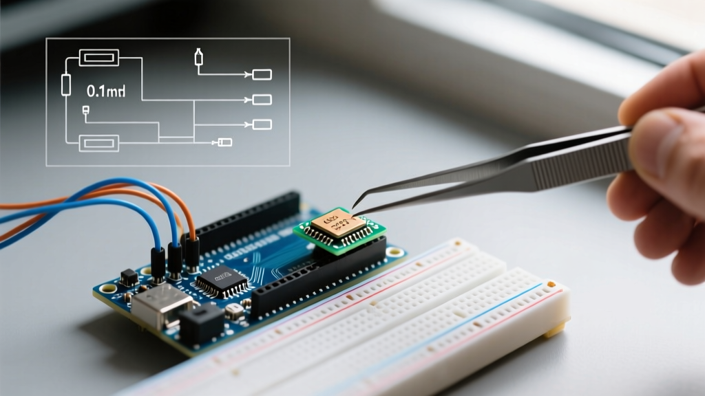
Expert Troubleshooting Tip: If your analog readings are drifting or highly erratic despite a clean sensor, add a 100nF X7R ceramic decoupling capacitor (e.g., Kemet C315C104K5R5TA) directly between the analog input pin and the Arduino GND pin. This creates a low-pass RC filter that stabilizes the voltage during the S/H acquisition window and shunts high-frequency EMI to ground.
Writing the C++ Code: Unlocking 14-Bit Mode
By default, the Arduino core attempts to maintain backward compatibility. If you simply call analogRead(A0) on an Uno R4, the IDE may return a 10-bit value (0-1023) by silently right-shifting the 14-bit hardware register, unless configured otherwise. To access the full hardware capabilities, you must explicitly invoke the analogReadResolution() function.
Core Implementation Sketch
// Precision ADC Reading for Arduino Uno R4 (14-bit)
const int sensorPin = A0;
const float vRef = 5.0; // Default VREF on Uno R4 Minima
const int maxAdcValue = 16383; // 2^14 - 1

void setup() {
  Serial.begin(115200);
  while (!Serial) { delay(10); }

  // CRITICAL: Unlock 14-bit hardware resolution
  analogReadResolution(14);

  // Optional: Use internal 2.5V reference for higher precision on low-voltage signals
  // analogReference(AR_INTERNAL2V5);
}

void loop() {
  int rawAdc = analogRead(sensorPin);

  // Calculate actual voltage
  float voltage = (rawAdc * vRef) / maxAdcValue;

  Serial.print("Raw 14-bit: ");
  Serial.print(rawAdc);
  Serial.print(" | Voltage: ");
  Serial.print(voltage, 4); // Print to 4 decimal places (0.3mV precision)
  Serial.println(" V");

  delay(100);
}
Advanced Calibration: Oversampling for 16-Bit Resolution
What if your project demands 16-bit precision, but you only have the Uno R4's 14-bit ADC? You can achieve this mathematically through a technique called oversampling. According to Nyquist and Shannon sampling theorems, oversampling combined with decimation can yield additional bits of resolution, provided there is at least 1 LSB of ambient thermal noise in the system to dither the signal.
The formula to gain n extra bits of resolution requires 4^n additional samples. To gain 2 extra bits (moving from 14-bit to 16-bit), you must sample the ADC 16 times, sum the results, and then divide by 4 (or bit-shift right by 2).
Oversampling Code Implementation
unsigned long read16BitAdc(int pin) {
  unsigned long sum = 0;
  // Take 16 samples (4^2) to gain 2 extra bits
  for (int i = 0; i < 16; i++) {
    sum += analogRead(pin);
    delayMicroseconds(200); // Allow S/H capacitor to reset and acquire
  }
  // Right-shift by 2 to decimate and scale back to 16-bit range (0-65535)
  return sum >> 2;
}
This technique is highly effective for slow-moving signals like ambient temperature monitoring or battery voltage tracking, where sampling speed is less critical than absolute precision.
Common Edge Cases and Troubleshooting
Even with perfect code, physical layer anomalies can ruin your data. Here are the most frequent edge cases encountered when deploying the adc on arduino in real-world environments:
- Floating Analog Pins: Never leave unused analog pins unconnected if you are reading them in a multiplexed loop. A floating pin acts as an antenna, picking up 50/60Hz mains hum and injecting noise into the ADC multiplexer, which can temporarily skew readings on adjacent pins. Always tie unused pins to GND via a 10kΩ pulldown resistor.
- USB Power Rail Noise: When powered via a PC USB port, the 5V rail is often plagued with high-frequency switching noise from the computer's motherboard. For precision ADC work, power the Uno R4 via the barrel jack using a regulated, low-ripple linear power supply (e.g., a 9V 1A linear adapter), allowing the board's onboard LDO to provide a cleaner 5V rail.
- VREF Mismatch: The Uno R4 Minima defaults to a 5V VREF, while the Uno R4 WiFi utilizes an internal architecture that may reference 3.3V depending on the specific board revision and jumper configurations. Always verify your board's VREF with a multimeter before hardcoding the
vRefvariable in your sketch.
Final Thoughts on Analog Acquisition
Mastering the adc on arduino requires moving beyond simple analogRead() calls and treating the analog pins as sensitive RF inputs. By respecting source impedance limits, implementing hardware RC filtering, leveraging the 14-bit capabilities of the modern RA4M1 architecture, and applying software oversampling, you can extract laboratory-grade data from a $20 microcontroller board. Whether you are building precision environmental sensors or calibrating custom motor controllers, these foundational analog principles will ensure your data is accurate, stable, and reliable.