
The Anatomy of a Water Pressure Transducer Failure
Integrating a water pressure transducer Arduino setup is a foundational task for automated hydroponics, reverse osmosis (RO) monitoring, and boiler control systems. The most common components used by makers are the ubiquitous 1/4-inch NPT brass transducers (often rated for 0-1.2 MPa or 174 PSI). While these generic sensors are highly cost-effective—typically retailing between $14 and $18—they are notorious for introducing severe analog noise, offset drift, and ADC saturation errors into microcontroller circuits.
Unlike simple digital sensors, these industrial-style transducers output an analog voltage that requires precise interpretation. When your serial monitor spits out erratic values, pegs at 1023, or slowly drifts over a 24-hour period, the issue rarely lies in the sensor's internal Wheatstone bridge. Instead, the fault usually stems from power rail instability, electromagnetic interference (EMI) from adjacent water pumps, or fundamental misunderstandings of ratiometric ADC mapping. This guide provides a deep-dive diagnostic framework to isolate and resolve these hardware and firmware anomalies.
The Ratiometric Reality: Understanding the 0.5V to 4.5V Output
Before troubleshooting, you must understand the electrical contract your sensor is making with the microcontroller. Standard 3-wire brass pressure transducers are ratiometric. They do not output an absolute voltage based on pressure; they output a percentage of their supply voltage (Vcc).
- Zero Pressure (Offset): 10% of Vcc (Typically 0.5V on a 5.0V rail)
- Full Scale Pressure: 90% of Vcc (Typically 4.5V on a 5.0V rail)
- Span: 80% of Vcc (4.0V total swing)
If your Arduino Uno's 5V USB rail sags to 4.8V due to a poor USB cable or an overloaded bus, your zero-pressure offset drops to 0.48V, and your full-scale drops to 4.32V. If your firmware hardcodes the 5.0V mapping constants, your calculated PSI will immediately skew by 4% to 5%. According to Arduino's official analog input documentation, relying on the default `analogRead()` without accounting for Vcc fluctuations is the primary cause of baseline drift in unregulated maker projects.
Diagnostic Matrix: Voltage vs. Pressure Mapping (100 PSI Sensor)
| Actual Pressure | Expected Voltage (at 5.00V Vcc) | Expected 10-Bit ADC Value | Common Error Symptom |
|---|---|---|---|
| 0 PSI | 0.500V | 102 | Reads 0 or negative (Wiring fault / GND lift) |
| 25 PSI | 1.500V | 307 | Erratic jumping (Pump EMI coupling) |
| 50 PSI | 2.500V | 512 | Gradual drift (Temperature / Dielectric shift) |
| 100 PSI | 4.500V | 921 | Clipped at 1023 (ESP32 ADC saturation) |
Symptom 1: Severe ADC Jitter and Ghost Readings
If your serial plotter looks like a jagged mountain range even when the water system is completely static, you are experiencing Electromagnetic Interference (EMI) and ground bounce. Water systems inherently rely on inductive loads—solenoid valves, diaphragm pumps, and centrifugal pumps. When these devices switch off, they generate massive back-EMF spikes that couple into high-impedance analog signal wires.
The Hardware Fix: Impedance Lowering and Bypassing
The analog input pin on an ATmega328P (Arduino Uno/Nano) has an internal sample-and-hold capacitor that requires a low-impedance source to charge fully within the ADC clock cycle. A long, unshielded wire acting as an antenna will prevent this capacitor from settling, resulting in jitter.
- Twisted Pair Routing: Never run the signal wire parallel to pump power lines. Use 22 AWG twisted pair cable for the Signal and GND lines to cancel out common-mode magnetic interference.
- Local Decoupling: Solder a 100nF (0.1µF) MLCC ceramic capacitor and a 10µF tantalum capacitor in parallel directly across the Vcc and GND pins at the sensor head, not just at the Arduino. This provides a local low-impedance charge reservoir.
- RC Low-Pass Filter: Insert a 10kΩ resistor in series with the signal wire, followed by a 100nF capacitor to ground at the Arduino pin. This creates a hardware low-pass filter with a cutoff frequency of roughly 159 Hz, instantly eliminating high-frequency pump noise.
Symptom 2: The ESP32 ADC Saturation Trap
Many modern makers bypass the Arduino Uno in favor of the ESP32 for built-in Wi-Fi telemetry. However, migrating a water pressure transducer Arduino circuit directly to an ESP32 without hardware modification guarantees failure at the upper pressure ranges.
Critical Architecture Warning: The ESP32's internal ADC (ADC1) is notoriously non-linear. Its effective, usable range is approximately 0.15V to 3.1V. Voltages above 3.1V will saturate the ADC, returning a hard-clipped value of 4095 (on the 12-bit scale), regardless of whether the actual input is 3.2V or 4.5V.
Because your 100 PSI transducer outputs up to 4.5V at maximum pressure, the ESP32 will blind you to any pressure above roughly 55 PSI. To diagnose and fix this, you have two professional-grade options:
- Option A (Precision Voltage Divider): Use a precision resistor network (e.g., 10kΩ and 15kΩ with 1% tolerance) to scale the 0.5V–4.5V signal down to 0.2V–1.8V. This keeps the signal well within the ESP32's linear sweet spot.
- Option B (External I2C ADC): Bypass the ESP32's internal ADC entirely. Wire an Adafruit ADS1115 breakout board (approx. $14.50) via I2C. The ADS1115 offers true 16-bit resolution, programmable gain amplifiers (PGA), and a rock-stable internal voltage reference, completely eliminating ESP32 non-linearity and Wi-Fi RF noise coupling.
Symptom 3: Gradual Offset Drift Over 24-48 Hours
If your system reads perfectly upon initial calibration but slowly reports higher pressures over a few days—even when the system is depressurized—you are likely facing thermal hysteresis or moisture ingress.
Generic brass transducers utilize a silicone oil-filled cavity to transfer force from the stainless steel diaphragm to the internal piezoresistive element. If the sensor is mounted in an environment with high ambient temperature swings (e.g., an unventilated greenhouse or near a water heater), the silicone oil expands, creating a false positive pressure reading. Furthermore, if the IP65 O-ring seal degrades, moisture can bridge the signal and ground pins on the internal PCB, creating a parallel resistance path that pulls the signal voltage down or up depending on the electrolytic galvanic reaction between the brass housing and the water.
Expert Recommendation: For mission-critical applications where drift is unacceptable, abandon the $15 generic brass sensors. Upgrade to an industrial-grade Amphenol NovaSensor NPI-19 or a TE Connectivity MSP300 series transducer. These cost between $45 and $85 but feature active temperature compensation circuits built directly into the ASIC, guaranteeing less than ±0.5% full-scale drift across a -20°C to 85°C range.
Advanced Troubleshooting: The 5-Step Isolation Protocol
When you are faced with a completely unresponsive or chaotic sensor, do not rewrite your firmware. Follow this hardware-first isolation protocol to identify the exact point of failure.
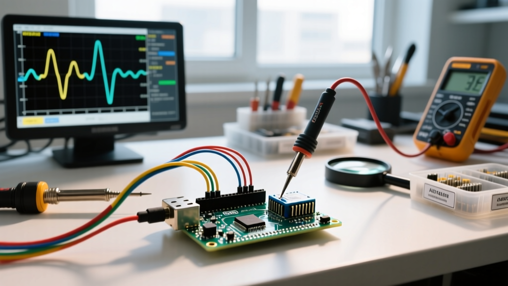
- The Multimeter Baseline Test: Disconnect the sensor from the Arduino. Power it with a dedicated, regulated bench power supply set to exactly 5.00V. Connect a digital multimeter (DMM) to the signal and ground pins. With zero pressure, it must read 0.50V (±0.02V). If it reads 0.0V or 5.0V, the internal bonding wire has snapped, or the Wheatstone bridge has burned out. Replace the sensor.
- The Ground Lift Check: Measure the voltage between the Arduino's GND pin and the sensor's GND pin while the circuit is under load. If you read more than 10mV of difference, you have a ground loop or undersized ground wiring. Run a dedicated, thick ground wire directly from the Arduino to the sensor.
- The Vcc Sag Test: Measure the 5V rail at the Arduino while a water pump activates. If the rail dips below 4.75V, the ATmega's internal voltage reference is shifting. Power the analog sensors from a dedicated Low Dropout Regulator (LDO) like the LM7805 or, better yet, a precision shunt reference like the LM4040.
- The Software Median Filter: Hardware filtering cannot catch every transient spike. Implement a software median filter. Instead of a simple `analogRead()`, take 15 rapid samples, sort them, and discard the top 5 and bottom 5 outliers before averaging the middle 5. This eliminates the impact of rare, high-amplitude EMI spikes without introducing the lag associated with standard moving averages.
- The Shielding Audit: As noted by analog design experts in Analog Devices' comprehensive guide on ADC grounding, high-impedance analog traces act as antennas. If your signal wire must run more than 2 feet, it must be routed through a grounded copper braided sleeve or a shielded CAT5e cable (using the drain wire for the shield, tied to ground at the Arduino end only to prevent ground loops).
Conclusion: Designing for Reliability
Achieving stable, laboratory-grade readings from a water pressure transducer Arduino setup requires respecting the physics of analog signal transmission. By acknowledging the ratiometric nature of the sensor, mitigating EMI through proper RC filtering and twisted-pair routing, and avoiding the ESP32's ADC saturation traps, you can transform a frustrating, erratic project into a robust, deployment-ready monitoring system. Always validate your hardware with a multimeter before blaming your code, and never underestimate the destructive power of pump back-EMF on unprotected microcontroller pins.