
The Case for Upgrading Your IR Sensor Hardware
When you first search for an infrared receiver Arduino tutorial, you are inevitably pointed toward the ubiquitous KY-022 sensor module. This module, built around the generic VS1838B photodiode chip, has been the default choice for hobbyists for over a decade. Priced at roughly $0.80 per unit on retail maker sites (and pennies in bulk), it works well enough for dimly lit living rooms. However, as maker projects in 2026 increasingly integrate with complex IoT ecosystems, motor-driven robotics, and outdoor enclosures, the limitations of the VS1838B have become glaringly apparent.
If your project suffers from phantom triggers, dropped packets near windows, or complete signal blindness when a fluorescent light flickers nearby, it is time for a hardware migration. This guide details the exact process of upgrading your legacy VS1838B setup to the industrial-grade Vishay TSOP34838, ensuring your remote-control logic remains bulletproof in any lighting condition.
Component Deep Dive: VS1838B vs. Vishay TSOP34838
Before we touch a soldering iron, it is critical to understand the architectural differences between these two 38kHz carrier-frequency receivers. The TSOP34838 is not just a 'better' version of the same chip; it utilizes a fundamentally different Automatic Gain Control (AGC) algorithm designed to suppress continuous optical noise.
| Specification | Generic VS1838B (KY-022) | Vishay TSOP34838 |
|---|---|---|
| Typical Retail Price (2026) | $0.80 (Module) / $0.15 (Bare) | $1.15 (Bare DIP/SMD) |
| Ambient Light Immunity | ~10,000 Lux (Fails in direct sun) | 150,000 Lux (Direct sunlight tolerant) |
| AGC Algorithm | Basic (Susceptible to continuous noise) | AGC3P (Suppresses fluorescent/LED flicker) |
| Internal Shielding | None (Exposed epoxy) | Integrated metal shield connected to GND |
| Minimum Burst Length | 6 cycles | 6 cycles (with strict gap requirements) |
| Supply Voltage Range | 2.7V to 5.5V | 2.5V to 5.5V |
Expert Insight: The primary failure mode of the VS1838B in modern maker spaces is its inability to filter out the high-frequency PWM noise emitted by modern LED light bulbs and dimmer switches. The TSOP34838's AGC3P algorithm specifically targets and ignores these continuous optical noise sources, preventing the receiver from 'deafening' itself.
Hardware Migration: Rewiring and Decoupling
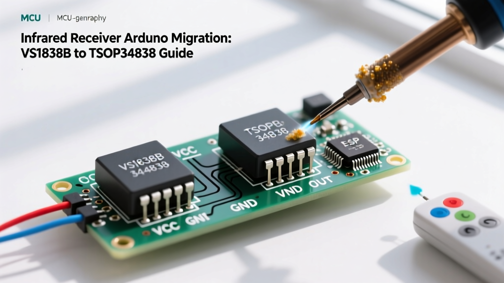
Migrating the physical hardware is relatively straightforward, as both components share a standard 3-pin footprint: VCC, GND, and OUT. However, the power delivery requirements dictate a change in your decoupling strategy. According to the Vishay IR Receiver Application Notes, improper decoupling is the number one cause of range degradation in high-performance IR receivers.
Step 1: Remove the KY-022 Module
Desolder the legacy KY-022 module. If you are using a breadboard, simply pull it out. Note that the pinout on some cheap KY-022 modules is mislabeled (often swapping VCC and GND on the silkscreen). Always verify the pinout of your new TSOP34838 against its datasheet before applying power.
Step 2: Implement the Dual-Capacitor Decoupling Network
The VS1838B is notoriously sensitive to voltage ripple, often causing the Arduino's I2C bus to hang if the sensor shares a 5V rail with a servo motor or an ESP8266 WiFi module. The TSOP34838 is more robust, but to achieve its rated 45-meter range, you must implement a dual-capacitor decoupling network directly at the sensor's pins.
- C1 (Ceramic): Place a 100nF (0.1µF) ceramic capacitor as close to the VCC and GND pins of the TSOP34838 as physically possible. This filters high-frequency switching noise from your microcontroller.
- C2 (Electrolytic): Place a 10µF to 47µF electrolytic capacitor in parallel with the ceramic capacitor. This acts as a local energy reservoir, preventing voltage sags when the sensor's internal amplifier spikes during heavy signal reception.
Step 3: Route the Output Pin
Connect the OUT pin of the TSOP34838 to your chosen digital interrupt pin on the Arduino. For an Arduino Uno R3 or Nano, Pin 2 or Pin 3 are ideal as they support hardware interrupts. For an Arduino Mega 2560, Pins 2, 3, 18, 19, 20, or 21 are valid. Ensure your trace length is under 15cm to prevent the wire from acting as an antenna for ambient EMI.
Firmware Migration: Adapting to IRremote v4.x
Hardware is only half the battle. If you are migrating an older project, your firmware is likely relying on deprecated versions of the IRremote library. As of 2026, the Arduino-IRremote GitHub repository has standardized on the v4.x API, which fundamentally changes how the receiver object is instantiated and polled.
Legacy Code (v2.x / v3.x) to Remove
#include

int RECV_PIN = 2;
IRrecv irrecv(RECV_PIN);
decode_results results;

void setup() {
  Serial.begin(9600);
  irrecv.enableIRIn(); // DEPRECATED
}

void loop() {
  if (irrecv.decode(&results)) { // DEPRECATED
    Serial.println(results.value, HEX);
    irrecv.resume(); // DEPRECATED
  }
}
Modernized Code (v4.x) Implementation
The modern API utilizes a globally instantiated IrReceiver object, eliminating the need to pass pointers to decode buffers and significantly reducing RAM overhead on ATmega328P chips.
#include

const uint8_t IR_RECV_PIN = 2;

void setup() {
  Serial.begin(115200);
  // Initialize with LED feedback enabled for debugging
  IrReceiver.begin(IR_RECV_PIN, ENABLE_LED_FEEDBACK);
}

void loop() {
  if (IrReceiver.decode()) {
    // Print the raw protocol and hex value
    Serial.print(F("Protocol: "));
    Serial.println(IrReceiver.decodedIRData.protocol);
    Serial.print(F("Hex Value: "));
    Serial.println(IrReceiver.decodedIRData.decodedRawData, HEX);

    // Crucial: Resume listening for the next packet
    IrReceiver.resume();
  }
}
Real-World Troubleshooting & Edge Cases
Even with premium Vishay silicon and updated firmware, environmental factors can introduce edge cases. Consult this troubleshooting matrix if your upgraded infrared receiver Arduino setup behaves erratically.
1. The 'Short Burst' Rejection Issue
Symptom: The TSOP34838 ignores signals from older, generic TV remotes, while the VS1838B accepted them.
Cause: The TSOP34838 features a strict 'short burst suppression' filter to ignore electrical sparks and optical noise. It requires a minimum burst length of 6 carrier cycles, followed by a gap of at least 10 cycles. Some ultra-cheap universal remotes output malformed 3-cycle bursts.
Solution: If you must support non-compliant legacy remotes, switch to the TSSP4038 series instead, which is designed for continuous IR beam breaking rather than strict remote-control protocol validation.
2. Cross-Talk in Multi-Sensor Arrays
Symptom: Building a robot with three IR receivers (e.g., for omnidirectional beacon tracking) results in overlapping data and bus collisions.
Cause: The output transistors of multiple receivers pulling the same interrupt line low simultaneously.
Solution: Do not wire multiple OUT pins to a single Arduino pin. Instead, use a hardware logical OR gate (like a 74HC32) if you only need to know if a signal is present, or assign each receiver to a dedicated Pin Change Interrupt (PCINT) on the ATmega328P, utilizing the Adafruit IR Sensor guidelines for software debouncing.
3. Range Drops When Transmitting and Receiving Simultaneously
Symptom: Your Arduino is acting as an IR blaster (transmitter) and receiver simultaneously. When the TX LED fires, the RX goes completely blind.
Cause: The 940nm TX LED is overwhelming the RX photodiode, and the current draw of the TX LED is causing a VCC brownout, resetting the RX AGC.
Solution: Isolate the TX LED circuit on a separate MOSFET driven directly from the battery rail, bypassing the Arduino's 5V linear regulator. Furthermore, implement software blanking: disable the receiver via IrReceiver.stop() during TX bursts, and re-enable it 50ms after transmission ceases to allow the AGC to recalibrate.
Final Verdict on the Migration
Migrating from the VS1838B to the Vishay TSOP34838 is one of the highest-ROI hardware upgrades you can make to an embedded control project. For an additional $0.35 per unit in bare component costs, you eliminate the most common points of failure in optical remote-control systems: ambient light saturation and power-rail noise. By pairing this premium hardware with the modern IRremote v4.x library, your Arduino-based IR interfaces will achieve industrial-level reliability, whether they are mounted in a sunlit greenhouse or a noisy server rack.