
The Definitive Arduino CNC Shield Pinout Map
Since its introduction, the Arduino CNC Shield V3 has remained the undisputed workhorse for DIY desktop routers, pen plotters, and laser engravers. However, as we move through 2026, the maker community has largely transitioned from loud, older stepper drivers to ultra-silent TMC2209 and TMC2226 chips. This shift has exposed several limitations in the classic shield design, prompting a wave of community-sourced wiring hacks and firmware patches.
In this community resource roundup, we synthesize the best wiring diagrams, GitHub repositories, and hard-won troubleshooting fixes from forums and maker spaces to give you the ultimate guide to the Arduino CNC shield pinout.
Core Pinout Breakdown: Uno to Shield Mapping
The V3 shield sits directly atop an Arduino Uno (or compatible ATmega328P board). It routes the ATmega's digital and analog pins to specific stepper, limit, and spindle functions. Below is the definitive mapping verified against the Protoneer Arduino CNC Shield original schematics.
| Arduino Pin | Shield Function | GRBL Default Mapping |
|---|---|---|
| D2 | X Step | X Axis Step Pulse |
| D3 | Y Step | Y Axis Step Pulse |
| D4 | Z Step | Z Axis Step Pulse |
| D5 | X Direction | X Axis Direction |
| D6 | Y Direction | Y Axis Direction |
| D7 | Z Direction | Z Axis Direction |
| D8 | Stepper Enable | Enable/Disable Motors |
| D9 | X Limit | X Limit Switch Input |
| D10 | Y Limit | Y Limit Switch Input |
| D11 | Z Limit | Z Limit Switch Input |
| D12 | Spindle Direction / Z+ Limit | Spindle Dir or 4th Axis |
| D13 | Spindle Enable / A-Dir | Spindle PWM/Enable |
| A0 | A Step (4th Axis) | A Axis Step Pulse |
| A1 | A Direction | A Axis Direction |
| A2 | Coolant Enable | Mist/Flood Coolant |
| A3 | Abort | Feed Hold / Cycle Start |
Community Hack: Integrating TMC2209 & TMC2226 Silent Drivers
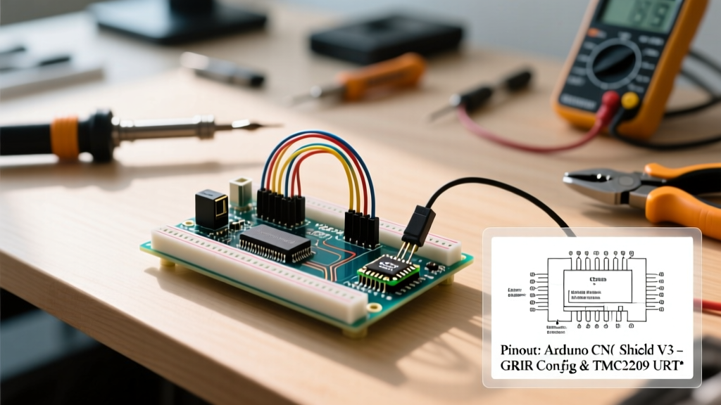
The most significant hurdle makers face in 2026 is adapting the V3 shield for Trinamic's silent stepper drivers. Unlike the older A4988 or DRV8825, the TMC2209 and TMC2226 require a UART serial connection to the microcontroller for advanced features like StallGuard (sensorless homing) and dynamic current control.
The UART Wiring Workaround
The standard V3 shield does not route UART pins to the stepper driver sockets. To enable UART mode, the community has standardized a hardware hack:
- Step 1: Bend the MS1 and MS2 pins on the TMC2209 driver inward so they do not insert into the shield's socket.
- Step 2: Solder a jumper wire from the TMC2209's MS1 pin (which acts as TX/RX in UART mode) to an available Arduino pin. The community consensus is to use the Z+ Limit pin (D12) or the Spindle Direction pin, as these are rarely used in standard 3-axis GRBL setups.
- Step 3: Configure GRBL or FluidNC to use SoftwareSerial on the chosen pin. According to the GRBL Configuration Wiki, modifying the
cpu_map.hfile is required to reassign these pins for UART communication rather than limit switching.
Expert Warning: When wiring UART lines, always place a 1kΩ resistor in series with the TX line to prevent back-feeding voltage into the Arduino's GPIO pins, a common failure mode reported on CNCZone forums.
Clone Board Pitfalls: Voltage & Logic Level Mismatches
While a genuine Protoneer board costs upwards of $28, generic V3 clones flood the market for $8–$12. These clones introduce specific electrical quirks that you must account for in your pinout and power wiring.
The VMOT Capacitor Issue
The V3 shield features a large electrolytic capacitor on the VMOT (motor voltage) rail. On cheap clones, this is often rated for only 25V or 35V, despite the board's silkscreen claiming a 45V tolerance. The community strictly advises capping your power supply at 24V DC. Pushing 36V into a clone board's VMOT pin will inevitably cause the capacitor to vent, destroying the trace and potentially sending high voltage back into your Arduino Uno's 5V rail via the stepper driver sockets.
Logic Level Shifting for 3.3V MCUs
If you are upgrading from an Arduino Uno (5V logic) to a 3.3V microcontroller like an ESP32 or Teensy 4.1 to run FluidNC, the V3 shield's optocouplers and pull-up resistors are tuned for 5V. You must bypass the onboard 5V pull-ups and supply a clean 3.3V reference to the logic side of the shield, or use a dedicated I2C/Logic level shifter between the MCU and the shield's header pins.
Hardware Compatibility Matrix (2026 Maker Standards)
Choosing the right stepper driver dictates how you interpret the shield's microstepping jumper pins. Here is how the community configures the MS1, MS2, and MS3 jumpers for modern drivers:
| Driver Model | Price (Approx) | Max Voltage | Jumper Config (MS1, MS2, MS3) | Microstepping |
|---|---|---|---|---|
| A4988 | $2.50 | 35V | All Jumpers IN | 1/16 |
| DRV8825 | $3.50 | 45V | All Jumpers IN | 1/32 |
| TMC2209 | $7.00 | 29V | All Jumpers OUT (UART) | Hardware 1/8, Interp 1/256 |
| TMC2226 | $9.50 | 29V | All Jumpers OUT (UART) | Hardware 1/8, Interp 1/256 |
Top Community GitHub Repositories for GRBL Tuning
Getting the pinout right is only half the battle; configuring the firmware is where most builds stall. We recommend bookmarking these community-maintained resources:
- gnea/grbl Official Repository: The absolute source of truth for GRBL v1.1. The wiki contains the exact C-preprocessor macros needed to invert the step/dir pins if your motors are running backward.
- FluidNC Wiki (GitHub): For makers migrating to ESP32-based CNC shields, FluidNC replaces GRBL and uses a YAML configuration file instead of C++ compilation. The community YAML templates for V3-compatible ESP32 shields are invaluable.
- OpenBuilds CONTROL Software: While not a GitHub repo, the OpenBuilds community forums host the most comprehensive database of GRBL
$$settings (like$100for steps/mm and$110for max feed rate) tailored to specific belt-and-pinion or leadscrew mechanical setups.
Expert Troubleshooting: Motor Stalls and Ghost Steps
When your pinout is correct but the machine behaves erratically, rely on this community-developed diagnostic flow:
- Ghost Steps (Motors twitching while idle): This is almost always EMI (Electromagnetic Interference) from the spindle VFD or router. Ensure your limit switch wires are shielded and routed away from the VMOT power lines. Add a 0.1µF ceramic capacitor across the limit switch signal and GND pins on the shield.
- One Axis Dead (No Step/Dir): Swap the stepper driver with a known working axis. If the dead axis moves, your driver is fried (common if hot-swapping drivers while VMOT is live). If it remains dead, check the Arduino socket header for cold solder joints on the D2-D7 pins.
- Hard Limit Alarms on Startup: GRBL defaults to Normally Closed (NC) limit switches. If you are using Normally Open (NO) microswitches, you must send the command
$5=1via the serial console to invert the limit pin logic in the firmware.
By combining the foundational Arduino CNC shield pinout with these modern community hacks, you can build a desktop CNC machine in 2026 that is quieter, more reliable, and far more capable than the original designs intended.