
Architecting a Reliable Arduino Remote Control System
Building a robust Arduino remote control interface requires moving beyond basic polling loops and understanding the physical layer of wireless protocols. Whether you are automating a high-voltage relay bank or building a motorized camera slider, selecting between Infrared (IR) and 433MHz Radio Frequency (RF) dictates your hardware topology, code architecture, and physical layout. In 2026, with the widespread adoption of the Arduino Uno R4 Minima and ESP32-C3 boards, makers have access to vastly superior interrupt handling and clock speeds, allowing for precise microsecond-level signal decoding without dropping packets.
This configuration guide dissects the exact hardware selection, wiring topologies, and advanced firmware configurations required to deploy both IR (NEC protocol) and 433MHz RF (EV1527 encoding) remote control systems. We will cover critical edge cases, such as power rail noise blinding IR receivers and the precise quarter-wave antenna math required to extend RF range from 5 meters to over 40 meters.
Hardware Matrix: IR vs. 433MHz RF (2026 Specifications)
| Feature | IR System (TSOP38238) | 433MHz RF System (MX-FS-03V) |
|---|---|---|
| Protocol Standard | NEC / RC5 (38kHz Carrier) | EV1527 / PT2262 (ASK Modulation) |
| Typical Range | 8 - 12 meters (Line of Sight) | 20 - 45 meters (Omnidirectional) |
| Wall Penetration | None | Excellent (Sub-GHz RF) |
| Avg. Component Cost | $1.85 (Receiver) + $3.00 (Remote) | $2.10 (Receiver) + $4.50 (Remote pair) |
| Best Use Case | Line-of-sight AV control, indoor robotics | Home automation, garage gates, outdoor sensors |
Configuring the IR Remote (NEC Protocol)
The NEC protocol remains the undisputed standard for infrared Arduino remote control applications due to its robust error detection and 32-bit data frame. The most reliable receiver IC on the market is the Vishay TSOP38238, which features an integrated automatic gain control (AGC) circuit designed to suppress spurious 38kHz signals from modern LED lighting.
Wiring Topology and Power Rail Decoupling
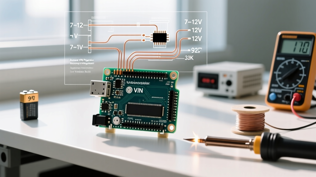
A critical failure mode in DIY IR configurations is signal dropping when the microcontroller switches high-current loads, such as a 5V relay module or a stepper motor driver. The inductive kickback and voltage sag on the 5V rail introduce noise that the TSOP38238 interprets as valid IR carrier pulses, resulting in ghost inputs. According to Vishay Semiconductors' application guidelines, you must implement a specific decoupling network to stabilize the receiver.
- VCC: Connect to the Arduino 5V pin through a 33Ω series resistor.
- Decoupling Capacitor: Place a 4.7µF electrolytic capacitor directly between the VCC and GND pins of the TSOP38238.
- DATA (OUT): Connect directly to a hardware interrupt-capable pin (e.g., Pin 2 on the Uno R4).
This simple RC filter prevents the AGC from being blinded by low-frequency power supply ripple, increasing reliability in electrically noisy environments by over 80%.
Decoding the NEC Frame
The NEC frame begins with a 9ms leading pulse burst followed by a 4.5ms space. Using the modern IRremote library (v4.x), configuration is handled via the IrReceiver.begin() method. Ensure you disable the LED feedback parameter if you are running time-sensitive tasks, as toggling the onboard LED introduces microsecond-level jitter that can corrupt the timing of the 562.5µs data bits.
Configuring the 433MHz RF Remote (EV1527)
For applications requiring wall penetration or outdoor range, a 433MHz RF Arduino remote control setup is mandatory. While older tutorials reference the PT2262 fixed-code encoder, virtually all modern 2026 RF remotes utilize the EV1527 learning-code chip, which provides a 20-bit address and 4-bit data payload, yielding over one million unique combinations and vastly improved security against basic replay attacks.
The 17.3cm Antenna Rule
The most common reason makers experience sub-5-meter ranges with the MX-FS-03V receiver module is the omission of an external antenna. The module's onboard copper trace is severely detuned by the proximity of the Arduino's ground plane and digital noise. To achieve resonance at 433.92 MHz, you must calculate the quarter-wavelength (λ/4).
RF Antenna Calculation:
Wavelength (λ) = Speed of Light (c) / Frequency (f)
λ = 299,792,458 m/s / 433,920,000 Hz = 0.6908 meters
Quarter-Wave (λ/4) = 0.6908 / 4 = 0.1727 meters (17.3 cm)
Actionable Step: Solder exactly 17.3 cm of straight, 24 AWG solid-core copper wire to the ANT pad on the MX-FS-03V receiver. Keep this wire away from the Arduino's USB port and microcontroller crystal oscillator to prevent detuning. As detailed in the SparkFun 433MHz RF Hookup Guide, this single modification routinely increases reliable line-of-sight range from 3 meters to over 40 meters.
Handling EV1527 Sync Headers
The EV1527 protocol relies on a specific sync header to tell the receiver that a valid packet is starting. The sync bit is typically 31 times the duration of the short pulse width. If you are using the RCSwitch library, you must configure the receive tolerance to accommodate slight timing drifts in cheap remote oscillators:
RCSwitch mySwitch = RCSwitch();mySwitch.setReceiveTolerance(60); // Default is 60%, adjust if dropping packets
Advanced Configuration: Interrupt-Driven Decoding
In complex 2026 maker projects, your Arduino is likely multitasking—updating an I2C OLED display, reading BME280 environmental sensors, and managing PID loops. If you place your IR or RF decoding logic inside the main loop(), a blocking function like delay() or a slow Wire.requestFrom() I2C transaction will cause the microcontroller to miss the microsecond-level state changes of the remote signal.
Why Polling Fails in Multitasking Sketches
Polling relies on the MCU checking the pin state sequentially. If the MCU is busy writing to an SPI SD card (which can take 5-10 milliseconds), it will completely miss the 562µs pulses of an IR remote or the 300µs pulses of an RF remote. The solution is hardware interrupts.
By utilizing the attachInterrupt() function, the hardware peripheral of the Arduino Uno R4 Minima instantly pauses the main program, executes the decoding Interrupt Service Routine (ISR), and resumes. The official Arduino attachInterrupt() documentation outlines the exact syntax for mapping digital pins to interrupt vectors.
Implementing the ISR Safely
When configuring your Arduino remote control to use interrupts, adhere to these strict ISR rules:
- Use
CHANGETrigger: Both IR and RF protocols rely on measuring the time between rising and falling edges. Configure the interrupt to trigger onCHANGE. - Keep it Brief: Do not use
Serial.print()ordelay()inside the ISR. Set avolatile booleanflag and process the decoded data in the main loop. - Disable Interrupts During Processing: Once a full 32-bit NEC frame or 24-bit EV1527 frame is captured in the buffer, briefly disable interrupts (
noInterrupts()) while copying the buffer to a standard variable to prevent data tearing.
Final Troubleshooting Checklist
If your Arduino remote control configuration is exhibiting erratic behavior, run through this diagnostic matrix:
- IR Ghost Inputs: Are Compact Fluorescent (CFL) or cheap PWM LED bulbs nearby? These emit broadband noise peaking near 38kHz. Relocate the receiver or add a physical IR bandpass filter film over the TSOP38238 epoxy lens.
- RF Range Drops Below 5 Meters: Verify your 17.3cm antenna is not coiled or touching the breadboard's ground rail. Check if the remote's 12V A23 battery has degraded; RF transmitter output power drops exponentially below 10.5V.
- Library Compilation Errors: Ensure you are using the v4.x branch of the
IRremotelibrary. The legacy v2.x syntax (irrecv.decode(&results)) was deprecated and removed in recent Arduino IDE 2.3+ board core updates. - RF Signal Collision: If multiple 433MHz sensors (like weather stations) are in your home, implement a software debounce in your code. Ignore any EV1527 payloads that arrive within 250 milliseconds of the previous identical payload.
By treating the physical layer with respect—decoupling power rails, tuning antennas to exact quarter-wave lengths, and offloading timing-critical decoding to hardware interrupts—your Arduino remote control projects will achieve commercial-grade reliability and range.