
The Core Question: Is the Arduino a Microcontroller?
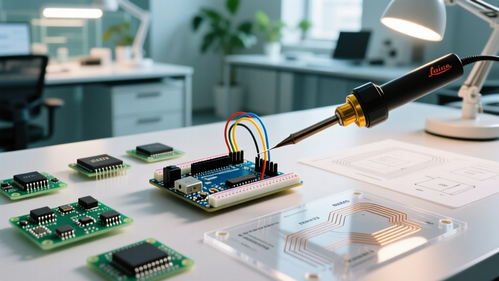
To answer the fundamental question directly: No, the Arduino itself is not a microcontroller. Arduino is a brand, an ecosystem, and a software IDE. The physical blue or green board you plug into your USB port is a development board (or evaluation kit). The actual microcontroller is the small, multi-legged black silicon chip mounted on that board. For example, on the classic Arduino Uno R3, the microcontroller is the Microchip (formerly Atmel) ATmega328P. On the newer Arduino Uno R4 Minima, it is the Renesas RA4M1 Arm Cortex-M4 chip.
Understanding this distinction is not just semantic trivia; it is the foundational step in workflow optimization for electrical engineers and advanced makers. Treating the entire development board as the final product leads to bloated Bill of Materials (BOM) costs, massive PCB footprints, and inefficient power consumption. By decoupling the 'Arduino ecosystem' from the 'Arduino development board,' you can transition seamlessly from rapid breadboard prototyping to highly optimized, standalone custom PCB production.
Anatomy of the Ecosystem: Dev Board vs. Silicon IC
To optimize your hardware workflow, you must understand what you are paying for when you buy a development board versus a raw integrated circuit (IC). The development board includes support circuitry that is essential for prototyping but entirely redundant in a finalized commercial product.
| Component | Arduino Uno R3 (Dev Board) | Raw ATmega328P-AU (Standalone IC) |
|---|---|---|
| Core Processor | ATmega328P-PU (DIP-28) | ATmega328P-AU (TQFP-32 SMD) |
| USB-to-Serial Bridge | ATmega16U2 (Requires own crystal & caps) | Not included (Use external FTDI/CH340 only for flashing) |
| Voltage Regulation | NCP1117 LDO (High quiescent current) | Custom LDO or direct battery feed (Optimized for uA sleep) |
| Footprint | 68.6 mm x 53.3 mm | 7 mm x 7 mm (IC only) |
| Approx. Unit Cost (2026) | $27.00 - $32.00 | $2.15 - $2.45 (Single unit DigiKey pricing) |
As highlighted in the Microchip ATmega328P Product Page, the raw silicon offers immense flexibility in packaging and power profiles that a rigid development board simply cannot provide.
Workflow Stage 1: Rapid Prototyping (The Dev Board Phase)
Your workflow should always begin with the development board. The Arduino Nano, Uno, or Mega exists to abstract away hardware complexities so you can validate your firmware logic, sensor integrations, and communication protocols (I2C, SPI, UART) without worrying about PCB layout errors.
Optimization Tip for Prototyping
Instead of using the bulky Uno, standardize your prototyping workflow around the Arduino Nano 33 IoT or the Seeed Studio XIAO SAMD21. These boards feature the powerful 32-bit ARM Cortex-M0+ architecture, castellated pads for easy surface-mount integration later, and a drastically smaller breadboard footprint. This allows you to write modern, 32-bit optimized C++ code that won't require a total rewrite when you move to production.
Workflow Stage 2: The Standalone Transition
Once your firmware is stable, the next phase of workflow optimization is stripping away the development board hardware. This is often called building a 'standalone Arduino.' The official Arduino documentation on breadboard setups provides a baseline, but professional workflows require stricter hardware design rules.
Critical Support Circuitry for Standalone ATmega328P
- Decoupling Capacitors: You must place a 100nF (0.1µF) MLCC capacitor as physically close as possible to every VCC and AVCC pin pair. In a TQFP-32 package, this means multiple caps. Skipping this leads to erratic ADC readings and spontaneous brown-out resets.
- Clock Source: If using an external 16MHz crystal, you need two 22pF load capacitors to ground. Workflow Hack: Replace the crystal and two caps with a single 16MHz ceramic resonator (e.g., Murata CSTCE series) to save board space and reduce BOM line items.
- Reset Pin Management: The RESET pin requires a 10kΩ pull-up resistor to VCC. For noisy industrial environments, add a 100nF capacitor from RESET to GND to prevent false triggers from EMI spikes.
Workflow Stage 3: Custom PCB Design & BOM Optimization
Moving to a custom PCB in KiCad or Altium Designer is where the true cost and footprint optimization occurs. Let us look at a real-world scenario for a 2026 IoT sensor node.
The BOM Reality Check:
Deploying 100 units using Arduino Pro Mini clones costs roughly $850 and requires manual header soldering and bulky enclosures. Designing a custom PCB using the ATmega328P-AU, an MCP1700-33 LDO, and a bespoke PCB antenna drops the BOM to $3.80 per unit, saving $470 on a 100-unit run while reducing the enclosure volume by 60%.
PCB Layout Rules for Microcontrollers
- Ground Planes: Never route the ground net as a thin trace. Use a continuous copper pour on the bottom layer for a solid ground plane. This lowers the impedance of the return path for high-frequency digital switching noise.
- Crystal Routing: Keep the traces from the MCU to the crystal/resonator as short as possible. Do not route any high-speed digital lines (like SPI MOSI or SCK) underneath the crystal to avoid capacitive coupling and clock jitter.
- Programming Pads: Instead of a bulky 6-pin ICSP header, use a 2x3 array of 1.27mm pitch test pads. Use a pogo-pin programming jig for flashing the bootloader and firmware during manufacturing. This saves $0.45 per unit in connector costs and eliminates a major point of mechanical failure.
Edge Cases: Fuse Bits and Bootloader Workflows
A major bottleneck in standalone workflows is mismanaging AVR fuse bits. The Arduino IDE hides these behind 'Board Definitions,' but when you design a custom PCB, you must program them directly using a tool like AVRDUDE and an ISP programmer (e.g., Atmel-ICE or a cheap USBasp).
Optimizing for Internal vs. External Clocks
If your application does not require precise UART baud rates or exact millisecond timing, you can eliminate the external crystal entirely and run the ATmega328P on its internal 8MHz oscillator. This saves $0.35 in BOM cost and frees up two GPIO pins (XTAL1 and XTAL2).
| Clock Configuration | Low Fuse (lfuse) | High Fuse (hfuse) | Extended Fuse (efuse) |
|---|---|---|---|
| External 16MHz Crystal | 0xFF | 0xDE | 0xFD |
| Internal 8MHz Oscillator | 0xE2 | 0xDA | 0xFD |
Warning: If you set the fuse bits to expect an external crystal but do not have one populated on your custom PCB, the microcontroller will 'brick' and refuse to communicate via ISP. You will need a high-voltage parallel programmer to rescue the chip. Always verify your clock circuit before writing fuse bits.
Summary: The Optimized Maker Workflow
Understanding that the Arduino is a development platform, not the microcontroller itself, fundamentally shifts how you approach electronic design. By starting with the dev board for firmware validation, transitioning to a standalone breadboard circuit for hardware verification, and finally designing a custom PCB with raw SMD microcontrollers, you optimize for cost, size, and power efficiency. For further reading on component selection and pricing, referencing distributor databases like the DigiKey ATmega328P-AU listing can help you track real-time silicon availability and lifecycle status as you scale your projects from the workbench to mass production.