
Integrating an Arduino motor shield into a robotics or automation project should be a plug-and-play experience, but hardware realities often interfere with software expectations. Whether you are using the classic BJT-based Arduino Motor Shield Rev3 (typically retailing around $32.00) or the I2C-driven Adafruit Motor Shield V2.3 ($24.95), drive errors, thermal throttling, and pin conflicts are common roadblocks. This guide bypasses generic advice and dives into the electrical and architectural specifics required to diagnose and fix stalled, twitching, or overheating motor setups in 2026.
Diagnostic Matrix: Symptom to Solution
Before grabbing a multimeter, cross-reference your setup's behavior with this diagnostic matrix to isolate the failure domain.
| Symptom | Suspect Component | Multimeter / Logic Check | Targeted Fix |
|---|---|---|---|
| Motor twitches but won't spin | Power Supply / Logic Rail | Measure VCC at shield terminals under load | Separate motor and logic power supplies; increase input voltage to compensate for H-Bridge drop |
| Shield gets excessively hot (>65°C) | L298N H-Bridge IC | Measure current draw in series (A) | Add forced-air cooling, attach aluminum heatsink, or upgrade to a MOSFET-based driver (e.g., TB6612FNG) |
| Motor spins one way only | Microcontroller Timer / Pins | Check PWM output on Pins 3 and 11 via oscilloscope or DMM | Remove Servo.h library; resolve Timer1/Timer2 hardware conflicts |
| Random shutdowns during stall | PTC Resettable Fuse | Test continuity across the polyfuse | Allow 5-10 mins for thermal reset; implement software current-limiting |
Deep Dive 1: The L298N Voltage Drop Reality
The most frequent complaint among makers is that a 12V DC gear motor connected to the official Arduino Motor Shield Rev3 spins sluggishly, even when powered by a 12V battery pack. The culprit is the STMicroelectronics L298N dual full-bridge driver.
Understanding BJT Saturation Losses
Unlike modern MOSFET-based drivers (like the TB6612FNG or DRV8871) which have an on-resistance ($R_{DS(on)}$) measured in milliohms, the L298N uses Bipolar Junction Transistors (BJTs). Current flowing through the motor must pass through two BJT junctions in series. According to the ST datasheet, the typical saturation voltage ($V_{CE(sat)}$) is 1.8V, but it can reach up to 3.2V at a 2A load.
Expert Insight: If you supply exactly 12.0V to the shield's power terminals, your 12V motor is actually receiving between 8.8V and 10.2V under load. This massive voltage drop results in a proportional loss of torque and RPM.
The Fix: Over-Voltage Compensation
To deliver a true 12V to your motor terminals, you must supply 14V to 15V to the shield's external power input. Ensure your power supply can handle the current spike; a 12V 5A switching power supply is ideal for dual-motor setups. If your motor's absolute maximum voltage rating is strictly 12V, abandon the L298N and wire up a Cytron MD10C or an Adafruit TB6612FNG breakout, which will drop less than 0.5V.
Deep Dive 2: PWM Pin Conflicts and Timer Hijacking
If your motor only spins in one direction, or if the speed control behaves erratically, you are likely experiencing a hardware timer collision on the Arduino Uno Rev3.
The Official Shield Pinout Trap
The Arduino Motor Shield Rev3 hardwires its functions to specific ATmega328P pins:
- Direction Channel A: Pin 12
- Direction Channel B: Pin 13
- PWM (Speed) Channel A: Pin 3 (Timer 2)
- PWM (Speed) Channel B: Pin 11 (Timer 2)
- Brake Channel A: Pin 9 (Timer 1)
- Brake Channel B: Pin 10 (Timer 1)
The Servo Library Collision
If your sketch includes the standard Servo.h library to control a steering mechanism alongside your drive motors, the library automatically hijacks Timer1. On the Uno, Timer1 governs Pins 9 and 10. While this directly affects the brake pins, modifying Timer1 prescalers can sometimes cause phase interrupts that destabilize the PWM generation on Timer2 (Pins 3 and 11) depending on the exact IDE version and compiler optimization flags.
Actionable Fix: Never use the standard Servo.h library when the official Motor Shield is stacked on an Uno. Instead, use the PWMServo library or manually reassign your servo to Pin 6 (Timer 0) or use an external I2C PCA9685 servo driver board to offload PWM generation entirely from the ATmega328P.
Deep Dive 3: Thermal Shutdown and the PTC Fuse
The Arduino Motor Shield Rev3 includes a polymeric positive temperature coefficient (PTC) resettable fuse to protect your microcontroller and USB port from catastrophic current backflow.
Identifying a Tripped Polyfuse
If your motors suddenly cut out during a high-torque maneuver (like a robot hitting a wall or a stall condition), the PTC fuse has likely tripped. The fuse on the official shield typically trips at 1.5A to 2.0A. When tripped, the resistance of the fuse spikes from a fraction of an ohm to several hundred ohms, effectively starving the shield of current.
- Disconnect Power: Remove both USB and external motor power.
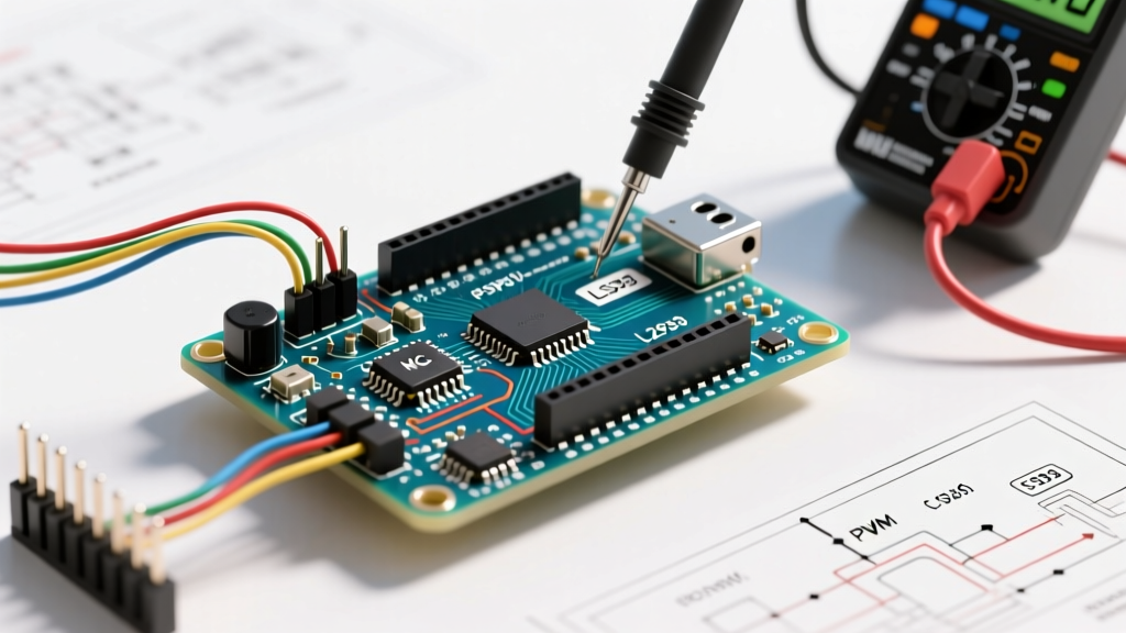
- Multimeter Test: Set your DMM to continuity or resistance mode. Probe across the PTC fuse (located near the power input terminals).
- Interpret Reading: A reading near
0.0Ωmeans the fuse is healthy. A reading in thekΩorOL(Open Loop) range means it is tripped.
Recovery Time: PTC fuses rely on thermal cooling to reset. You must wait 5 to 10 minutes at room temperature for the polymer matrix to contract and restore conductivity. To prevent recurring trips, implement a software routine that monitors the shield's onboard current sense pins (A0 for Channel A, A1 for Channel B). If the analog reading exceeds 400 (approx. 1.6A), trigger an immediate software brake and reverse sequence to clear the mechanical stall.
Deep Dive 4: I2C Ghosting on the Adafruit V2.3 Shield
For makers using the Adafruit Motor Shield V2.3, the architecture is vastly different. It utilizes a PCA9685 I2C PWM controller and TB6612FNG MOSFET drivers. Because it communicates via I2C, it is immune to the pin conflicts mentioned above, but it introduces a new failure mode: I2C bus capacitance and ghosting.
The 30cm Wire Limit
If you are daisy-chaining multiple shields or running long I2C jumper wires to a Raspberry Pi or secondary microcontroller, the capacitance on the SDA and SCL lines increases. The PCA9685 operates at a default I2C address of 0x60. High capacitance rounds off the sharp square-wave edges of the I2C clock signal, causing the microcontroller to miss ACK (acknowledge) bits. This results in the motor shield randomly ignoring speed commands or defaulting to full speed.
Hardware Pull-Up Remediation
The Adafruit shield includes onboard 10kΩ pull-up resistors. However, for wire runs exceeding 30cm, 10kΩ is too weak to pull the line high fast enough before the next clock cycle.
- The Fix: Solder additional 4.7kΩ or 2.2kΩ pull-up resistors between the SDA/SCL lines and the 5V rail directly at the microcontroller end of the cable.
- Software Check: Use the Arduino
I2CScannersketch. If0x60appears intermittently or shows up as multiple phantom addresses (e.g.,0x60,0x61,0x64), your bus is suffering from signal reflection and requires the stronger pull-ups mentioned above.
Summary Checklist for 2026 Builds
Before deploying your motor-driven project into the field, verify these three critical parameters:
- Voltage Headroom: Have you accounted for the 2V-3V BJT drop if using an L298N shield?
- Timer Isolation: Is your code free of standard Servo library interrupts that collide with hardware PWM timers?
- Current Sense Integration: Are you actively reading analog pins A0/A1 to detect stalls before the physical PTC fuse trips?
By treating the motor shield not just as a passthrough board, but as an active electrical component with distinct physical limitations, you can eliminate 95% of the drive errors that plague intermediate robotics projects.