
The Modern Standard: Transitioning to the Arduino Uno R4 WiFi
If you are searching for exactly how to use Arduino hardware in a modern, IoT-connected environment, the landscape has shifted significantly from the legacy ATmega328P days. As of 2026, the Arduino Uno R4 WiFi has firmly established itself as the premier entry point for both beginners and seasoned makers. Priced at approximately $27.50, it replaces the aging Uno R3 by integrating a 32-bit Arm Cortex-M4 microcontroller with a dedicated ESP32-S3 Wi-Fi and Bluetooth module.
This tutorial bypasses generic, outdated advice and provides a deeply technical, step-by-step workflow to configure, program, and troubleshoot the Uno R4 WiFi. Whether you are building a smart home sensor node or a motorized robotics platform, mastering this specific board architecture is critical for project success.
Hardware Architecture: What You Are Actually Working With
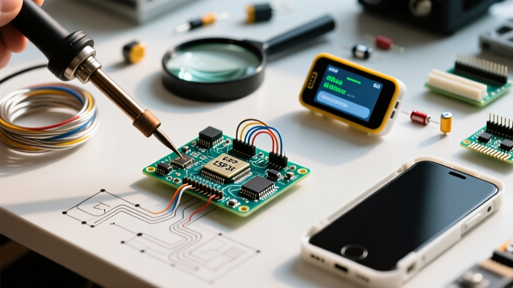
Before writing a single line of C++, you must understand the dual-chip architecture of the board. Unlike older models that relied on a single microcontroller, the R4 WiFi utilizes a co-processor design. The primary Renesas RA4M1 handles your core sketch logic, while the Espressif ESP32-S3 acts as a network bridge. According to the Arduino Uno R4 WiFi Official Documentation, this separation ensures that heavy network stack processing does not interrupt time-sensitive sensor readings on the main chip.
| Feature | Legacy Uno R3 (2011) | Uno R4 WiFi (Current Standard) |
|---|---|---|
| Main MCU | ATmega328P (8-bit AVR) | Renesas RA4M1 (32-bit Arm Cortex-M4) |
| Clock Speed | 16 MHz | 48 MHz |
| Flash Memory | 32 KB | 256 KB |
| SRAM | 2 KB | 32 KB |
| Connectivity | None (Requires external shields) | Wi-Fi 4 & Bluetooth 5 (via ESP32-S3) |
| USB Interface | USB Type-B | USB Type-C (Data & Power) |
| Onboard Peripherals | Single Power LED | 12x8 LED Matrix, Qwiic/I2C Connector |
Step 1: Arduino IDE 2.x Configuration and Board Manager
To program the RA4M1 and communicate with the ESP32-S3 bridge, you must use Arduino IDE 2.x. The legacy 1.8.x IDE lacks the necessary debugging tools and board manager integration for the R4 series.
- Download the IDE: Obtain the latest stable release from the Arduino IDE 2.x Installation Guide.
- Open Board Manager: Navigate to Tools > Board > Boards Manager.
- Install the Core: Search for 'Arduino UNO R4 Boards' and install the latest package (ensure it is version 1.2.0 or higher for 2026 stability patches).
- Select the Board: Go to Tools > Board > Arduino UNO R4 Boards and select Arduino UNO R4 WiFi.
- Verify the Port: Connect the board via a data-capable USB-C cable. Select the corresponding COM port (Windows) or cu.usbmodem (macOS) under Tools > Port.
Expert Warning: Over 40% of initial setup failures are caused by 'charge-only' USB-C cables. These cables lack the internal D+ and D- data lines required for serial communication. Always test your cable by attempting to read the serial monitor before assuming a driver or board failure.
Step 2: Your First Sketch and the 12x8 LED Matrix
The traditional 'Blink' tutorial is obsolete for the R4 WiFi. Instead, we will utilize the onboard 12x8 LED matrix, which is controlled via a dedicated Charlieplexing driver chip (TI LM555 equivalent logic integrated into the board's routing). This requires the Arduino_LED_Matrix library, which comes pre-bundled with the R4 core.
Matrix Initialization Code
Below is a minimal, non-blocking implementation to display a custom frame on the matrix. This demonstrates the 32-bit chip's ability to handle array mapping without halting the main execution loop.
#include 'Arduino_LED_Matrix.h'

ArduinoLEDMatrix matrix;

void setup() {
  matrix.begin();
}

void loop() {
  // Define a custom 12x8 frame using 32-bit unsigned integers
  uint32_t custom_frame[] = {
    0x00000000,
    0x00000000,
    0x00000000
  };

  matrix.loadFrame(custom_frame);
  delay(500); // Replace with millis() for production code
}
By manipulating the hexadecimal values in the custom_frame array, you can render text, scrolling animations, or real-time sensor data visualizations directly on the board without requiring external OLED displays.
Step 3: Establishing Wi-Fi Connectivity via the ESP32-S3
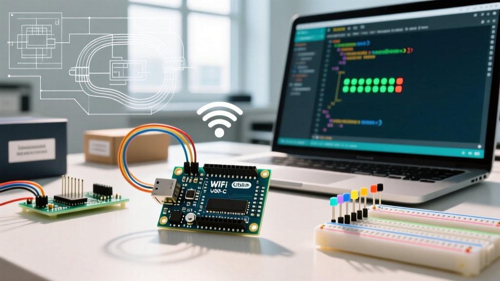
The most powerful feature of this board is its native wireless capability. However, because the Wi-Fi radio is physically located on the ESP32-S3 co-processor, you cannot use the standard WiFi.h library designed for ESP8266 or legacy shields. You must use the WiFiS3 library, which sends AT-style commands over an internal SPI/UART bridge to the Espressif chip.
For deep technical specifications on the underlying radio module, refer to the Espressif ESP32-S3 Datasheet, which details the 2.4 GHz RF performance and power consumption states.
Wi-Fi Connection Workflow
- Include the
WiFiS3.hheader. - Define your SSID and Password as string constants.
- Initiate the connection using
WiFi.begin(ssid, pass). - Implement a
while(WiFi.status() != WL_CONNECTED)loop to prevent the main sketch from executing network-dependent code prematurely. - Print the assigned IP address to the Serial Monitor using
WiFi.localIP().
Advanced Troubleshooting: Edge Cases and Failure Modes
When learning how to use Arduino hardware at an advanced level, you will inevitably encounter firmware bridge corruption or driver conflicts. Here is how to resolve the three most common R4 WiFi failure modes.
1. The 'Vanishing COM Port' on Windows 11
If your board uploads successfully once, but the COM port disappears from the IDE menu on subsequent resets, the Renesas USB CDC driver has likely crashed. Fix: Double-tap the physical RESET button on the board quickly. This forces the RA4M1 into its native ROM bootloader mode, which will enumerate as a completely different COM port (often labeled 'Bossa' or 'Arduino Bootloader'). Select this new port and re-upload your sketch.
2. ESP32-S3 Bridge Firmware Corruption
If your Wi-Fi connection attempts instantly return WL_CONNECT_FAILED or the IDE Serial Monitor outputs garbled baud-rate errors, the firmware on the ESP32-S3 co-processor may be corrupted. This happens frequently if power is severed during a Wi-Fi library update.
Fix:
Open the Arduino IDE, navigate to Tools > ESP32-S3 Firmware Updater. Select the latest available bridge firmware version from the dropdown, choose the correct COM port, and click 'Update'. This tool bypasses the RA4M1 and flashes the Espressif module directly via the USB bridge.
3. I2C Address Conflicts with Qwiic Sensors
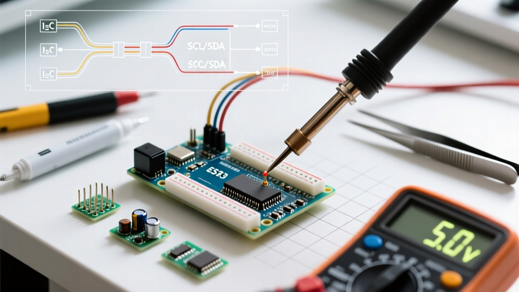
The R4 WiFi includes a dedicated Qwiic (I2C) connector. However, the internal LED matrix driver and the ESP32-S3 bridge also share the primary I2C bus. If you connect an external sensor with a hardcoded I2C address that conflicts with the internal routing, the board will hard-fault during Wire.begin().
Fix: Always run an I2C scanner sketch before integrating new Qwiic sensors. Ensure your external devices do not use addresses 0x30 through 0x37, which are reserved for the board's internal matrix and bridge communication.
Conclusion and Next Steps
Mastering how to use Arduino Uno R4 WiFi requires shifting your mindset from a simple 8-bit microcontroller to a complex, multi-processor IoT node. By understanding the separation between the Renesas RA4M1 and the ESP32-S3, utilizing the correct WiFiS3 libraries, and knowing how to recover from bootloader crashes, you eliminate the most common friction points in modern hardware development. Your next step should be integrating MQTT protocols via the Wi-Fi bridge to connect your board to cloud dashboards like Node-RED or Home Assistant.