
The Engineering Case for the PS3 Arduino Interface
Integrating a Sony DualShock 3 (PS3) controller into an Arduino-based robotics or telemetry project remains one of the most cost-effective control solutions available. Unlike modern Bluetooth Low Energy (BLE) gamepads, the PS3 controller utilizes Bluetooth Classic (HID profile), offering a robust 125Hz to 250Hz polling rate, 6-axis gyroscopic data, pressure-sensitive buttons, and dual analog sticks. However, because standard Arduino boards lack native Bluetooth Classic HID host capabilities, configuring a PS3 Arduino interface requires precise hardware selection and library management.
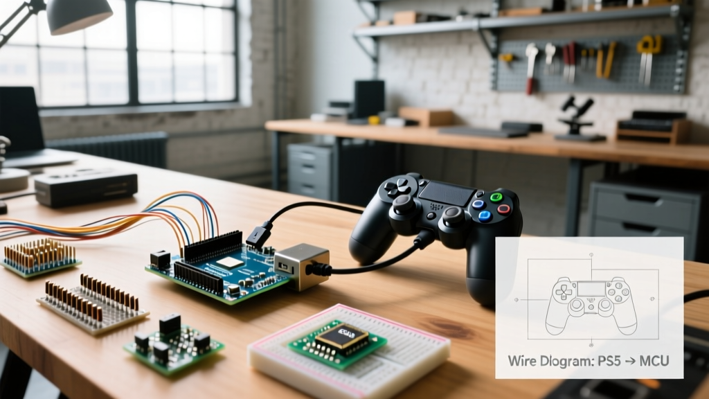
This configuration guide details the exact hardware stack, power management protocols, and pairing sequences required to establish a low-latency wireless link between an Arduino Uno R3 and a PS3 DualShock 3 controller using a USB Host Shield.
Hardware Bill of Materials (BOM) & 2026 Sourcing
Hardware selection is the most common point of failure in this build. The market is currently saturated with clone components that lack the necessary firmware support for HID host mode. Below is the verified BOM for a stable configuration.
| Component | Specific Model / Requirement | Est. Price (2026) | Critical Notes |
|---|---|---|---|
| Microcontroller | Arduino Uno R3 (Rev3) or Mega 2560 | $27.00 | Must have standard ICSP headers for Shield SPI communication. |
| Interface Shield | USB Host Shield 2.0 (Circuits@Home compatible) | $15.00 - $22.00 | Ensure the 5V/3.3V voltage regulator jumper is correctly set. |
| Bluetooth Dongle | CSR8510 A10 (Genuine Cambridge Silicon Radio) | $8.00 - $12.00 | Avoid generic "BT 4.0" dongles; they often use unsupported Realtek chips. |
| Controller | Sony DualShock 3 (Model: CECHZC2U) | $35.00 (Refurb) | Third-party PS3 clones do not support the standard HID pairing handshake. |
| Power Supply | 5V 2A DC Barrel Jack Adapter | $6.00 | Required to prevent onboard voltage regulator thermal throttling. |
Phase 1: Power Configuration and Thermal Management
Before uploading any code, you must address the power delivery architecture. The standard Arduino Uno relies on an onboard AMS1117-5.0 linear voltage regulator to step down barrel jack input to 5V. This regulator has a strict thermal limit and can safely supply only about 500mA of continuous current.
Expert Warning: A Bluetooth dongle draws approximately 80mA-120mA during active HID polling. The USB Host Shield logic draws roughly 50mA. If you connect the PS3 controller via USB to charge its internal 3.7V Li-Po battery while operating the shield, the current draw will exceed 700mA, triggering the Arduino's thermal shutdown or permanently damaging the AMS1117 regulator.
Actionable Configuration: For mobile rover applications, bypass the Arduino's onboard regulator. Use a dedicated 5V 2A UBEC (Universal Battery Elimination Circuit) or a high-efficiency buck converter wired directly to the Arduino's 5V and GND pins. This ensures the USB Host Shield receives clean, stable voltage without thermally stressing the microcontroller board.
Phase 2: Library Installation and MAC Address Pairing
The PS3 controller does not broadcast its presence to random Bluetooth hosts; it must be cryptographically paired to the host's MAC address. We utilize the industry-standard USB Host Shield 2.0 Library by felis to manage the HCI (Host Controller Interface) and HID protocols.
Step-by-Step Pairing Sequence
- Library Setup: Open the Arduino IDE. Navigate to Sketch > Include Library > Manage Libraries. Search for and install
USB Host Shield 2.0. - Dongle Initialization: Insert the genuine CSR8510 A10 Bluetooth dongle into the USB-A port on the Host Shield. Connect the Arduino to your PC via USB for programming.
- Upload Host Sketch: Open File > Examples > USB_Host_Shield_2.0 > Bluetooth > PS3BT. Upload this sketch to the Arduino.
- Extract Host MAC: Open the Serial Monitor at 115200 baud. The shield will initialize the dongle and print its Bluetooth MAC address (e.g.,
00:1B:DC:0F:28:A5). Note this address. - Controller Handshake: Without unplugging the Bluetooth dongle, connect the PS3 controller to the USB Host Shield using a Mini-USB data cable. Press the PS button on the controller.
- EEPROM Bonding: The Serial Monitor will display a pairing sequence. The library automatically writes the dongle's MAC address into the PS3 controller's internal EEPROM. Once it reads
Connected, the pairing is complete. - Wireless Verification: Disconnect the Mini-USB cable. Press the PS button on the controller. The four red LEDs on the controller will flash, then settle on a single solid LED, indicating a successful Bluetooth Classic HID connection.
Phase 3: Data Mapping and Deadzone Calibration
Raw analog data from the PS3 controller ranges from 0 to 255, with the mechanical center resting at 128. Direct mapping of this data to motor controllers results in severe "stick drift" due to mechanical potentiometer tolerances. You must implement a software deadzone.
Below is a highly optimized C++ helper function to map the PS3 analog sticks to a standard -100 to 100 PWM range, incorporating a configurable deadzone to eliminate idle jitter.
int mapPS3Stick(int rawValue, int deadzone) {
  int center = 128;
  int minVal = 0;
  int maxVal = 255;

  // Apply Deadzone
  if (abs(rawValue - center) <= deadzone) {
    return 0;
  }

  // Map to -100 to 100 scale
  if (rawValue > center + deadzone) {
    return map(rawValue, center + deadzone, maxVal, 0, 100);
  } else {
    return map(rawValue, minVal, center - deadzone, -100, 0);
  }
}

void loop() {
  Usb.Task();
  if (PS3.PS3Connected) {
    int leftY = mapPS3Stick(PS3.getAnalogHat(LeftHatY), 12); // 12 is deadzone
    // leftY is now cleanly mapped from -100 (forward) to 100 (reverse)
  }
}
Troubleshooting Matrix: Common Failure Modes
Even with correct wiring, the PS3 Arduino stack is prone to specific environmental and hardware failures. Refer to this diagnostic matrix before assuming your microcontroller is defective.
| Serial Monitor Output / Symptom | Root Cause Analysis | Configuration Fix |
|---|---|---|
OSC did not start |
The MAX3421E USB controller on the shield is not communicating via SPI. Often caused by missing ICSP headers or incorrect 5V/3.3V jumper settings on clone shields. | Verify the shield is fully seated. Ensure the VCC jumper on the shield is set to 5V if using a 5V Arduino Uno. |
| Dongle Not Recognized (No MAC printed) | Counterfeit Bluetooth chip. Many cheap dongles use Realtek or Broadcom chips that lack the specific HCI vendor commands required by the felis library. | Source a verified CSR8510 A10 dongle. Alternatively, consult the Circuits@Home Hardware Manual for supported Atheros alternatives. |
| Connects via USB, Drops on Wireless | Insufficient 5V current on the shield's USB port to power the dongle's RF transmitter during the initial handshake burst. | Inject external 5V power directly into the shield's VCC pin. Do not rely on PC USB power for mobile deployment. |
| High Latency / Missed Button Presses | The Usb.Task() function is being delayed by blocking code (e.g., delay() or long I2C sensor reads) in the main loop. |
Remove all delay() calls. Use millis() for timing. Usb.Task() must execute at least every 10ms to maintain the HID interrupt pipe. |
Modern Context: Why Not Use an ESP32?
A common question in 2026 is whether the ESP32 can replace the Uno + USB Host Shield stack for PS3 controllers. While the ESP32 hardware natively supports Bluetooth Classic, the standard Arduino ESP32 core does not expose an easy-to-use HID Host API for legacy gamepads without utilizing complex third-party frameworks like Bluepad32 or the ESP-IDF directly. For makers who require a rapid, reliable, and heavily documented configuration using standard Arduino IDE libraries, the Uno R3 paired with the Arduino USB Host Shield remains the most robust and deterministic architecture for PS3 integration.
Final Calibration Checklist
- Verify external 5V power is supplying at least 1.5A to the shield.
- Confirm the Serial Monitor baud rate is strictly set to 115200.
- Ensure the PS3 controller firmware is updated (requires a PS3 console or PC tool like ScpToolkit prior to Arduino pairing).
- Implement the deadzone mapping function to protect downstream motor drivers from idle voltage.