
Why Build a Custom Arduino Rev Counter?
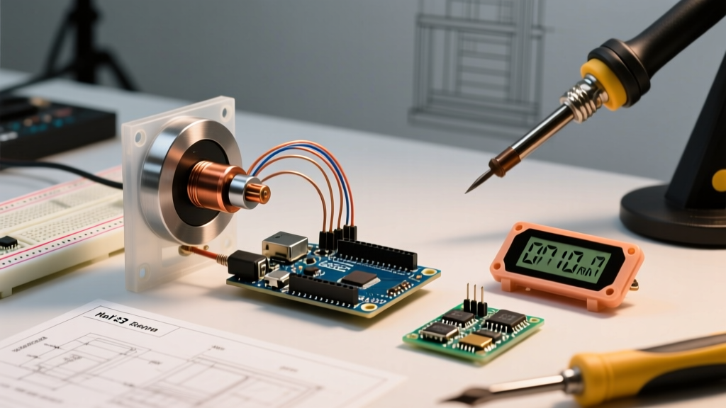
Whether you are monitoring the spindle speed of a DIY CNC router, tracking the RPM of a small engine, or logging the velocity of a motorized winch, a reliable tachometer is essential. While commercial digital tachometers exist, they often lack data-logging capabilities or cost upwards of $150. Building an arduino rev counter gives you complete control over the sampling rate, display output, and serial data streaming, all for under $35 in components.
In this 2026 guide, we will move beyond basic polling methods that fail at high speeds. We will design an interrupt-driven, hardware-debounced RPM measurement system using an Arduino Uno R4 Minima, an A3144 Hall effect switch, and an I2C OLED display.
Bill of Materials (2026 Edition)
To ensure high-resolution pulse detection without signal degradation, we are skipping the cheap KY-024 linear sensor modules in favor of a raw, digital Hall effect switch.
| Component | Specific Model / Value | Est. Price (2026) | Purpose |
|---|---|---|---|
| Microcontroller | Arduino Uno R4 Minima | $20.00 | Main processing unit with 48MHz Cortex-M4 |
| Sensor | Allegro A3144 Hall Switch | $1.50 (5-pack) | Digital magnetic pulse detection |
| Display | 128x64 SSD1306 I2C OLED | $7.50 | Real-time visual RPM readout |
| Magnet | N52 Neodymium (5x2mm) | $4.00 | Triggers the Hall sensor per revolution |
| Debounce Filter | 10kΩ Resistor & 100nF Capacitor | $0.15 | Hardware RC low-pass filter |
The Physics and Math of RPM Calculation
Revolutions Per Minute (RPM) is fundamentally a measurement of frequency. If your rotating shaft has one magnet attached, the sensor outputs one pulse per revolution. The formula to convert pulse counts into RPM over a specific time window is:
RPM = (Pulse Count × 60,000,000) / (Elapsed Time in µs × Pulses Per Revolution)
At 10,000 RPM with a single magnet, the sensor generates roughly 166 Hz (166 pulses per second). While a standard digitalRead() loop can theoretically handle this, introducing display updates, serial logging, and I2C bus communication will cause the microcontroller to miss pulses. This is why we must use hardware interrupts.
The Secret to Accuracy: Hardware Debouncing
The most common failure mode in DIY tachometer projects is 'phantom pulses.' When the magnetic field transitions across the A3144's threshold, the internal Schmitt trigger can oscillate for a few microseconds, registering as 2 or 3 distinct interrupts instead of one. This results in wildly inflated RPM readings at low speeds.
Implementing the RC Filter
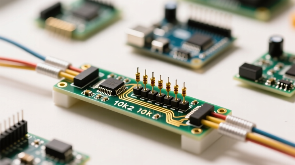
Rather than relying on software debouncing (which adds latency and limits maximum RPM tracking), we will implement a hardware RC (Resistor-Capacitor) low-pass filter directly on the sensor's output pin.
- Pull-up Resistor: Connect a 10kΩ resistor between the A3144 OUT pin and 5V.
- Filter Capacitor: Connect a 100nF (0.1µF) ceramic capacitor between the OUT pin and GND.
This creates a hardware debounce with a time constant (τ) of approximately 1 millisecond. It cleanly smooths the rising edge of the pulse, ensuring the Arduino receives exactly one clean logic LOW transition per magnet pass. For a deeper dive into Hall effect switching characteristics, refer to the Texas Instruments Hall-Effect Sensor Application Note.
Wiring the Hardware
Below is the exact pinout for the Arduino Uno R4 Minima. Note that the R4 series requires careful attention to I2C pull-ups, though most modern SSD1306 breakout boards include onboard 4.7kΩ pull-up resistors.
| Component Pin | Arduino R4 Minima Pin | Notes |
|---|---|---|
| A3144 VCC | 5V | Do not use 3.3V; A3144 requires 4.5V minimum |
| A3144 GND | GND | Shared ground with OLED and Cap |
| A3144 OUT (Filtered) | Digital Pin 2 | Hardware Interrupt 0 (INT0) |
| SSD1306 SDA | A4 (SDA) | I2C Data Line |
| SSD1306 SCL | A5 (SCL) | I2C Clock Line |
Writing the Interrupt-Driven Firmware
To capture high-speed pulses without blocking the main loop, we utilize the attachInterrupt() function. According to the Arduino attachInterrupt() Reference, variables modified inside an Interrupt Service Routine (ISR) must be declared as volatile to prevent the compiler from optimizing them out of memory.
Core Logic Flow
- ISR Trigger: Every time Pin 2 goes LOW (magnet detected), the ISR increments a pulse counter and records the current
micros()timestamp. - Main Loop: Every 250 milliseconds, the main loop calculates the elapsed time, computes the RPM, updates the OLED, and resets the pulse counter.
- Display Update: We use the Adafruit SSD1306 library. To prevent I2C bus locking, we only push data to the screen 4 times per second. See the Adafruit Monochrome OLED Breakouts Guide for library installation.
Handling Micros() Overflow
The micros() function overflows and resets to zero approximately every 70 minutes. If an overflow occurs between the start and end of our measurement window, the elapsed time calculation will result in a massive negative number, causing the RPM calculation to fail. Always use unsigned long math and allow natural rollover, or implement a simple check: if (currentTime < lastTime) { currentTime += 4294967295; }.
Calibration and Edge Cases
Even with perfect code, physical realities dictate the accuracy of your arduino rev counter. Here are the edge cases you must account for during calibration:
1. Magnet Placement and Orientation
The A3144 is highly directional. The magnetic field lines must pass perpendicular to the face of the sensor. Mounting the N52 magnet flat against the side of a shaft (axial magnetization) works best. Ensure the air gap between the magnet and the sensor face is exactly 2mm to 4mm. Any wider, and high-speed vibrations may pull the magnet out of the sensor's detection threshold, causing missed pulses.
2. Multi-Pole Configurations
If you are measuring a gear with 12 teeth, or a shaft with 4 magnets, you must update the pulsesPerRev variable in your code to 12 or 4, respectively. This multiplies your resolution by that factor, allowing for much more stable RPM readings at low speeds (e.g., below 100 RPM).
3. I2C Display Lag
Pushing a full 128x64 pixel buffer over I2C at 100kHz takes roughly 15 milliseconds. If you attempt to update the display inside the ISR or on every single loop iteration, you will introduce severe latency and potentially crash the I2C bus. Always decouple the sensor reading (ISR) from the display rendering (Main Loop timer).
Troubleshooting Common RPM Errors
- Reading is exactly double the actual RPM: Your hardware RC debounce filter is missing or the capacitor value is too low. The sensor is triggering on both the approaching and receding edges of the magnetic field, or contact bounce is occurring. Verify the 100nF capacitor is correctly bridging the OUT pin and GND.
- Reading drops to zero at high speeds: The magnet is passing too quickly for the A3144's internal switching time (typically 2µs, but can be longer if the magnetic field is weak). Move the sensor closer to the magnet or use a stronger N52 neodymium magnet.
- OLED flickers or shows garbage data: The I2C bus is suffering from capacitance issues or noise injected by the motor you are measuring. Add 4.7kΩ pull-up resistors to both SDA and SCL lines, and ensure the Arduino's GND is tied directly to the motor controller's GND to equalize reference voltages.
Conclusion
By combining a digital Hall effect switch, a hardware RC debounce filter, and interrupt-driven firmware, you transform a basic microcontroller into an industrial-grade tachometer. This arduino rev counter setup is robust enough to handle the electrical noise of brushless motor controllers and the mechanical vibrations of small combustion engines, providing reliable data for your most demanding maker projects.