
The Evolution of Arduino Keypad Integration
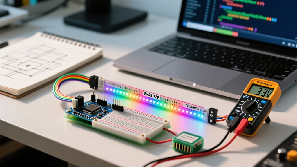
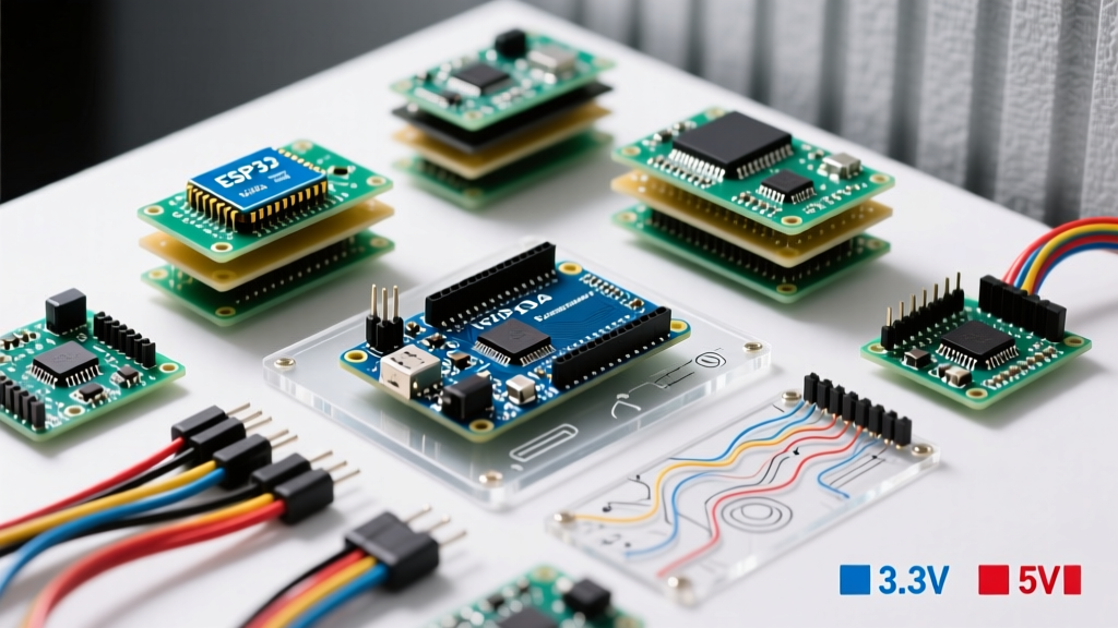
Selecting the right arduino keypad for your project is no longer as simple as plugging a 4x4 membrane into an Arduino Uno. As of 2026, the maker ecosystem has heavily shifted toward 3.3V logic architectures (like the ESP32-S3, Raspberry Pi Pico, and Nano 33 IoT), making voltage compatibility, pin starvation, and ADC resolution critical factors in keypad selection. A mismatched interface can lead to unresponsive inputs, ghosting, or worse, permanent GPIO damage from 5V backfeeding.
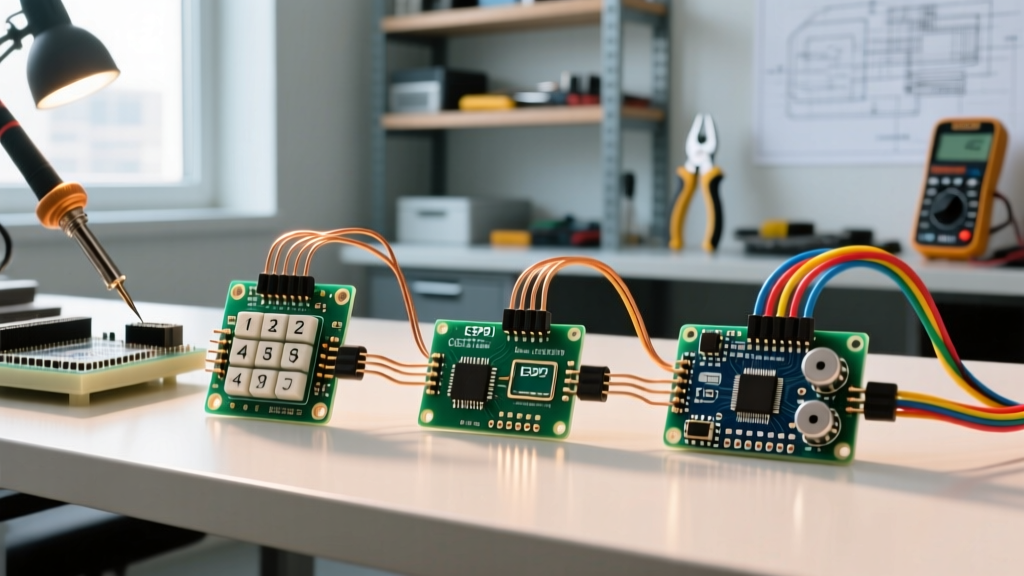
This comprehensive compatibility guide breaks down the three primary keypad interfaces—Digital Matrix, I2C, and Analog Resistor Ladders—and maps their compatibility across modern microcontroller units (MCUs).
The Three Primary Keypad Interfaces
Before wiring a single pin, you must understand the electrical topology of your chosen keypad module. Each interface trades off pin count, processing overhead, and hardware complexity.
1. Digital Matrix (The Classic 4x4 / 3x4)
Matrix keypads arrange switches in a grid of rows and columns. A standard 4x4 membrane keypad requires 8 GPIO pins to read 16 buttons. The microcontroller sequentially pulls rows LOW while reading columns to detect closures. While ubiquitous and cheap (typically $2.00 to $3.50), they are pin-hungry and require careful logic-level management on 3.3V boards.
2. I2C Keypads (The Pin-Saver)
I2C keypads utilize an onboard expander IC (commonly the PCF8574, MCP23017, or a dedicated capacitive touch controller like the MPR121) to translate button presses into I2C data packets. They require only 4 wires (VCC, GND, SDA, SCL) regardless of the number of keys. Prices range from $6.00 for basic PCF8574-backed mechanical boards to $18.00 for premium capacitive glass interfaces.
3. Analog Resistor Ladder
Analog keypads use a series of voltage dividers. Pressing a button routes a specific resistance to the analog-to-digital converter (ADC) pin, yielding a unique voltage. They require only 1 analog pin for up to 16 buttons. However, they are highly susceptible to temperature drift, resistor tolerance variations, and ADC non-linearity.
MCU Compatibility & Voltage Matrix
The most common failure mode in modern keypad projects is ignoring logic-level thresholds. Below is a compatibility matrix detailing how different MCU families in 2026.
| Microcontroller | Logic Level | Matrix (Direct) | I2C (Expander) | Analog (ADC) | Primary Risk Factor |
|---|---|---|---|---|---|
| Arduino Uno R4 Minima | 5V Tolerant | Native (Safe) | Native (Safe) | 14-bit (Excellent) | None. Ideal for all types. |
| ESP32-S3 / C3 | 3.3V Only | Requires Level Shifter | Native (3.3V I2C) | 12-bit (Non-linear) | 5V backfeed frying GPIOs. |
| Raspberry Pi Pico (RP2040) | 3.3V Only | Requires Level Shifter | Native (3.3V I2C) | 12-bit (Good) | ADC ground offset errors. |
| Arduino Nano 33 IoT | 3.3V Only | Requires Level Shifter | Native (3.3V I2C) | 12-bit (Good) | Pin starvation (Matrix). |
Deep Dive: Matrix Keypads and the Ghosting Problem
When using the industry-standard Arduino Playground Keypad Library, the MCU scans the matrix by setting one row LOW at a time and reading the columns. If you are building a security door lock or a macro-pad where multiple keys might be pressed simultaneously, you will encounter ghosting.
Solving Ghosting with Diodes
Ghosting occurs when three keys forming a rectangle are pressed, causing current to backflow through the fourth intersection, registering a false fourth keypress. To achieve N-Key Rollover (NKRO), you must solder a standard 1N4148 signal diode in series with every single switch cathode. This prevents reverse current flow. While membrane keypads do not support this modification, mechanical PCB-mount keypads (like the DFRobot 4x4 mechanical module, ~$14.50) often include diode pads on the PCB underside.
The 3.3V Pull-Up Trap
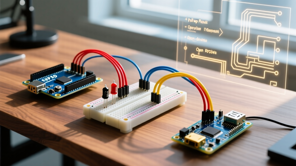
If you connect a 5V matrix keypad to an ESP32 and enable the ESP32's internal pull-up resistors, the 3.3V GPIO pin will be pulled up to 3.3V. However, if the keypad module has onboard 10kΩ pull-up resistors tied to a 5V VCC line, you will force 5V directly into the ESP32's 3.3V GPIO, eventually degrading the silicon. Always inspect the keypad PCB for onboard pull-ups and des them or cut the VCC trace if interfacing with 3.3V logic.
I2C Keypads: Expander ICs and Pull-Up Calculations
I2C keypads are the optimal choice for pin-starved boards like the ATtiny85 or when building complex IoT dashboards. However, not all I2C expanders are created equal.
PCF8574 vs. MCP23017
The NXP PCF8574 is a quasi-bidirectional I/O expander frequently found on cheap 4x4 I2C keypad modules ($4.00 - $7.00). It lacks internal pull-up resistors and relies on weak internal current sources. If your I2C bus capacitance exceeds 100pF (common when using ribbon cables longer than 30cm), the signal edges will degrade, causing missed keystrokes. In these scenarios, you must add external 4.7kΩ pull-up resistors to both SDA and SCL lines tied to VCC.
For higher reliability, the Microchip MCP23017 offers true bidirectional GPIOs, configurable internal 100kΩ pull-ups, and interrupt pins (INTA/INTB). Using the INT pin allows the MCU to sleep and only wake upon a keypress, a critical feature for battery-operated ESP32 keypad locks.
Analog Keypads: The ADC Resolution Bottleneck
Analog resistor ladder keypads are deceptively simple but mathematically treacherous. They output a specific voltage based on the closed switch. The MCU reads this via `analogRead()`.
Tolerance Stacking and Overlapping Bands
Most cheap analog keypads ($1.50 - $3.00) use 5% tolerance resistors. On a 10-bit ADC (0-1023), a 5% variance might shift a reading by ±15 points. If your code uses tight `switch/case` bands (e.g., `case 510 to 520`), temperature changes or resistor drift will cause misreads. Always implement wide tolerance bands in your code (e.g., `if (val > 490 && val < 540)`).
Furthermore, the ESP32's 12-bit ADC is notoriously non-linear at the extreme ends of its range (near 0V and near 3.3V). If your analog keypad outputs 3.1V for the '1' button, the ESP32 may read it erratically. To fix this, add a voltage divider to scale the maximum keypad output down to 2.8V, keeping it within the ESP32's linear ADC zone.
Logic Level Translation: Protecting Your 3.3V MCUs
As highlighted in SparkFun's Logic Levels Guide, mixing 5V and 3.3V devices requires careful translation. If you must use a legacy 5V matrix keypad with a 3.3V Raspberry Pi Pico or ESP32, do not rely on simple resistor dividers for the output lines, as they will slow down the scanning frequency and cause debounce errors.
Instead, use a dedicated bidirectional logic level converter based on the BSS138 MOSFET (available from Adafruit or SparkFun for ~$3.95). Alternatively, for unidirectional column-reading lines, a CD4050 non-inverting buffer powered at 3.3V will safely clamp the 5V matrix outputs down to safe 3.3V logic highs without sacrificing the microsecond-level scanning speed required by the Keypad library.
Summary and 2026 Purchasing Recommendations
Choosing the correct arduino keypad depends entirely on your host MCU's architecture and your physical design constraints:
- For 5V Boards (Uno R4, Mega 2560): Standard 4x4 membrane matrix keypads remain the most cost-effective and robust choice. Use the standard `Keypad.h` library.
- For 3.3V IoT Boards (ESP32, Pico): Skip the matrix wiring headaches. Invest in an I2C keypad module utilizing the MCP23017 or a capacitive touch interface like the MPR121. Ensure your I2C pull-ups are tied to the 3.3V rail.
- For Ultra-Low Pin Count (ATtiny85): Analog resistor ladders are mandatory, but you must map the ADC values empirically using a serial monitor before hardcoding the thresholds, accounting for your specific board's VCC variance.
Pro-Tip for 2026: If you are designing a custom PCB for a commercial product, abandon mechanical matrix keypads entirely. Capacitive touch ICs (like the Azoteq IQS series or Microchip MPR121) eliminate mechanical bounce, seal the enclosure against moisture, and communicate cleanly over I2C, drastically reducing assembly costs and field failure rates.