
Selecting the correct headers for Arduino boards and custom shields is a foundational step in any embedded electronics project. Whether you are assembling a custom sensor breakout, stacking multiple shields on an Uno R3, or designing a permanent installation, the mechanical and electrical integrity of your pin connections dictates the reliability of the entire system. In this comprehensive quick reference guide, we break down the exact specifications, soldering protocols, and failure modes associated with standard 2.54mm headers, updated with current 2026 component availability and pricing.
Quick Reference: Standard Header Specifications
The vast majority of the Arduino ecosystem relies on the imperial 0.1-inch (2.54mm) pitch standard. Below is the baseline specification matrix for standard through-hole headers used in maker and prototyping environments.
| Parameter | Standard Specification | Notes & Tolerances |
|---|---|---|
| Pitch | 2.54 mm (0.1") | Industry standard; do not confuse with 2.0mm pitch used on some ESP32/SAMD boards. |
| Current Rating | 3.0A per pin (max) | Continuous current; derate to 1.5A for high-temp environments (>80°C). |
| Voltage Rating | 250V AC/DC max | More than sufficient for 3.3V and 5V logic systems. |
| Housing Material | PBT or High-Temp Nylon | Must withstand 260°C+ wave soldering temperatures without warping. |
| Contact Plating | Gold flash over Nickel | Prevents oxidation; tin plating is cheaper but prone to tin whiskers. |
| Standard Pin Length | 11.0 mm total | Typically 3.0mm below housing, 8.0mm above housing. |
Types of Headers for Arduino Ecosystems
1. Standard Breakaway Male Headers
These are the ubiquitous 1x40 pin strips found in almost every starter kit. As of 2026, generic gold-plated breakaway strips cost between $0.10 and $0.15 per 40-pin strip on bulk marketplaces, while premium Samtec or Harwin equivalents from authorized distributors like DigiKey cost around $1.20 to $1.80 per strip. They are used for mounting sensors, adding pin access to custom PCBs, and terminating jumper wires.
2. Pass-Through Stacking Headers (Female)
Essential for the Arduino shield ecosystem. Stacking headers feature extra-long male pins (typically 10.5mm or 15mm) that pass completely through the female receptacle. This allows you to solder the header to a shield while leaving enough pin exposed underneath to plug into the base Arduino board. A complete R3 Shield stacking set (1x8, 1x10, 2x6) typically retails for $2.95 to $4.50 from vendors like Adafruit or Pololu.
3. Right-Angle (R/A) Headers
Used when vertical clearance is restricted, such as inside low-profile 3D-printed enclosures. R/A headers route connections horizontally. When using R/A headers, pay strict attention to the pin offset (the distance from the PCB surface to the center of the pin), which is usually 2.54mm or 4.3mm depending on the manufacturer.
The Arduino Uno R3 Header Pinout Matrix
When designing shields or ordering replacement headers for Arduino Uno R3 boards, you must match the exact asymmetric pin counts. The standard R3 layout consists of four distinct header blocks:
- Power/Analog Block: 1x8 pins (IORF, AREF, GND, A0-A5)
- Digital Block 1: 1x10 pins (D0-D7, RX/TX)
- Digital Block 2: 1x8 pins (D8-D13, GND, AREF - wait, AREF is on the other side. Correct: D8-D13, GND, IOREF)
- ICSP Header: 2x3 pins (SPI bus and reset, strictly 2.54mm pitch)
Critical Design Note: The distance between the Digital Block 1 (1x10) and Digital Block 2 (1x8) on an official Uno R3 is exactly 48.26mm (1.9 inches). If you are designing a custom shield PCB, verify this dimension in your CAD software to prevent mechanical binding.
Step-by-Step Soldering Protocol for Perfect Alignment
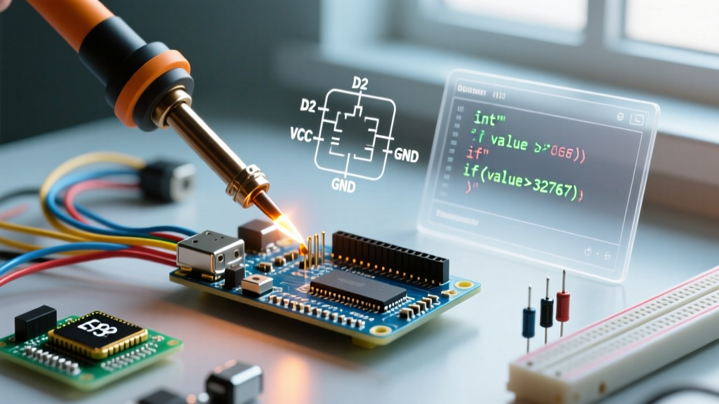
Soldering headers requires precision to ensure the plastic housing sits perfectly flush against the PCB. Misaligned headers will cause mechanical stress when mating with DuPont cables or shields. For a deep dive into foundational soldering skills, refer to the SparkFun Through-Hole Soldering Tutorial.
- Preparation: Set your soldering station to 340°C (644°F) if using 60/40 leaded rosin-core solder (0.8mm diameter). If using lead-free SAC305, increase to 370°C (698°F). Always use a 2.4mm chisel tip; conical tips lack the thermal mass for rapid through-hole heat transfer.
- The Breadboard Trick (For Male Headers): Push the short ends of the male header strip into a standard solderless breadboard. This holds the pins perfectly perpendicular to the PCB. Place your Arduino or shield board onto the long pins, ensuring it sits flush.
- Tack One Corner: Apply the iron to the pad and pin of one corner pin. Feed a tiny amount of solder to create a tack joint. Remove the iron and let it cool for 3 seconds.
- Verify Plumb: Inspect the board from two orthogonal angles. If the header is leaning, reheat the tacked pin and gently push the plastic housing until it sits flush and straight.
- Solder Remaining Pins: Move to the opposite corner, then solder the rest. Dwell time should not exceed 1.5 to 2 seconds per pin to prevent melting the PBT housing or lifting the PCB pad.
For advanced flux techniques and tip maintenance, the Adafruit Guide to Excellent Soldering provides excellent visual references for identifying proper wetting and fillet shapes.
Common Failure Modes & Troubleshooting
Even experienced makers encounter issues when installing headers for Arduino projects. Here is how to diagnose and fix the most common failures:
Solder Wicking and Bridging
Symptom: Solder climbs too far up the pin, or bridges the 2.54mm gap between adjacent pins.
Cause: Excessive solder volume, lack of flux, or using an iron tip that is too large.
Fix: Apply liquid no-clean flux to the bridged pins. Use a high-quality copper solder wick (2.0mm width) with a clean, tinned chisel tip to draw the excess solder away. Never use a solder sucker on fine-pitch headers, as the mechanical shock can lift the plated through-hole (PTH) barrel.
Melted or Warped Plastic Housing
Symptom: The black plastic spacer melts, pushing down over the pins or deforming.
Cause: Dwell time exceeded 3 seconds per pin, or the iron temperature was set above 400°C.
Fix: Prevention is the only cure. If a housing melts, you must desolder the entire strip, clean the holes, and install a fresh header. Melted PBT can outgas and weaken the solder joint.
Cold Joints and Poor Wetting
Symptom: The solder forms a dull, grainy ball that does not flow into a smooth, concave fillet.
Cause: The pad or pin was not heated sufficiently before introducing the solder wire.
Fix: Reheat the joint, add a microscopic amount of fresh leaded solder (which contains fresh flux) to lower the melting point and promote flow, then remove the iron and hold the board perfectly still until the solder solidifies.
Frequently Asked Questions (FAQ)
Can I use 2.0mm pitch headers on a standard Arduino?
No. Standard Arduino boards (Uno, Mega, Nano) strictly use 2.54mm (0.1") pitch. 2.0mm headers are common on specific microcontroller breakout boards like the Raspberry Pi Pico or certain ESP32-C3 modules. Attempting to force a 2.0mm header into a 2.54mm footprint will result in misaligned pins and immediate mechanical failure.
How do I safely remove a soldered header without damaging the Arduino pads?
Use a desoldering braid (copper wick) and a high-thermal-mass chisel tip. Coat the pins in generous amounts of tacky flux. Press the wick over the pins, apply the iron on top of the wick, and wait for the solder to liquefy and absorb into the copper. Once all pins are free, the header will drop out. Never pry the header off with a flathead screwdriver while the solder is semi-solid; you will rip the copper annular rings right off the FR4 fiberglass.
Are gold-plated headers worth the extra cost?
For indoor, climate-controlled prototyping, standard tin-plated headers are perfectly adequate. However, if your Arduino project is deployed in high-humidity environments, outdoors, or subject to frequent mating/unmating cycles, gold-flash over nickel plating is highly recommended. Gold prevents oxidation, ensuring low contact resistance over the lifespan of the device.
What is the purpose of the IOREF pin on the R3 header?
The IOREF (I/O Reference) pin provides the voltage reference for the microcontroller's logic levels (either 5V or 3.3V). Smart shields read this pin to automatically configure their level shifters and voltage regulators, ensuring safe communication between a 5V Uno and a 3.3V shield. For more details on shield compatibility and hardware revisions, consult the official Arduino Uno R3 documentation.
Why do my female jumper wires feel loose on the male headers?
Cheap, mass-produced DuPont jumper wires often use stamped metal contacts with poor spring tension, which wear out after 10-15 insertion cycles. If you are building a permanent installation, bypass jumper wires entirely and solder directly to the header pins, or invest in premium silicone-jacketed cables with machined beryllium-copper contacts that maintain grip over thousands of cycles.