
The Anatomy of an LED Failure on Arduino
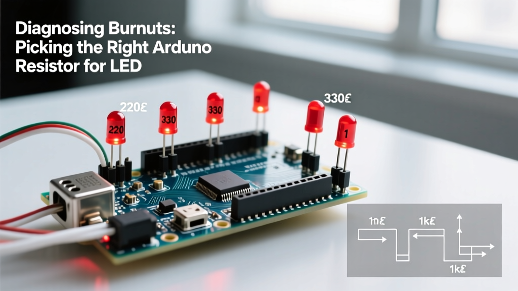
You wired up a simple circuit, uploaded the classic Blink sketch, and were greeted by one of three frustrating outcomes: the LED flashed once and died, it glows with a pathetic dimness, or your microcontroller pin is now unresponsive. Diagnosing these hardware errors almost always traces back to a single, fundamental oversight: selecting the wrong arduino resistor for led current limiting. While modern microcontrollers are remarkably resilient, treating an LED as a simple resistive load rather than a non-linear diode is a fast track to component failure.
To diagnose LED circuit errors effectively, we must first understand the electrical boundaries of the microcontroller. The standard ATmega328P found on the Arduino Uno and Nano has an absolute maximum DC current rating of 40mA per I/O pin, with a recommended continuous operating current of 20mA. Furthermore, the total current drawn across all pins must not exceed 200mA. When you omit a current-limiting resistor, or select one with an inadequate ohmic value, the LED attempts to draw as much current as the power supply can provide, quickly exceeding these silicon thresholds and causing thermal runaway.
Symptom 1: The 'Flash and Die' (Catastrophic Burnout)
The Error: You connect a standard 5mm LED directly to a 5V Arduino pin, or use a resistor value that is far too low (e.g., 10 ohms). The LED emits a blindingly bright flash for a fraction of a second, then goes permanently dark. In severe cases, the microcontroller pin is also destroyed.
The Diagnosis: LEDs do not obey Ohm's Law linearly. They have a specific Forward Voltage (Vf) threshold. For a standard red LED, this is roughly 1.8V to 2.0V. Once the applied voltage exceeds this threshold, the internal resistance of the LED drops to near zero. If you apply 5V directly, the remaining 3.0V to 3.2V has nowhere to go but to drive an infinite theoretical current through the diode junction. The LED's internal bond wire melts, or the silicon junction physically ruptures.
According to the official Arduino Uno Rev3 documentation, exceeding the 40mA absolute maximum rating per pin causes irreversible electromigration within the AVR silicon, effectively burning out the internal MOSFET that drives the pin. If your LED died and the pin no longer registers digital writes, you have likely damaged the ATmega328P.
Symptom 2: The 'Ghost Glow' (Dim or Flickering Output)
The Error: The LED lights up, but it is unusually dim, or it flickers erratically when using PWM (Pulse Width Modulation) on pins like 3, 5, 6, 9, 10, or 11.
The Diagnosis: This error is typically caused by overestimating the required resistance, or by failing to adjust your resistor calculations when migrating from a 5V board (Uno/Mega) to a 3.3V board (Arduino Zero, Due, or ESP32). If you use a 330-ohm resistor calculated for a 5V system on a 3.3V ESP32 with a Blue LED (Vf = 3.2V), the voltage differential is only 0.1V. Pushing 0.1V through 330 ohms yields a mere 0.3mA of current—far below the 20mA required for full illumination.
Expert Warning: When diagnosing dim LEDs on 3.3V architectures like the ESP32, remember that many GPIO pins have strict lower current limits. Some ESP32 pins can only safely source 12mA. Always verify the specific datasheet for your exact MCU variant before lowering your resistor values to compensate for dimness.
The Definitive Arduino Resistor for LED Matrix
To eliminate calculation errors, use the reference matrix below. These values assume a target continuous current of 20mA, which provides optimal luminosity without stressing the microcontroller or the LED junction. The values are derived using the standard formula: R = (V_source - V_forward) / I_target.
| LED Color | Typical Vf (Volts) | Target Current | Resistor for 5V Logic (Uno/Nano) | Resistor for 3.3V Logic (Zero/ESP32) |
|---|---|---|---|---|
| Red | 1.8V - 2.0V | 20mA | 150Ω to 160Ω | 68Ω to 75Ω |
| Yellow / Orange | 2.0V - 2.2V | 20mA | 140Ω to 150Ω | 56Ω to 68Ω |
| Green (Standard) | 2.2V - 2.4V | 20mA | 130Ω to 150Ω | 47Ω to 56Ω |
| Blue / White | 3.0V - 3.4V | 20mA | 82Ω to 100Ω | Cannot drive directly from 3.3V pin* |
*Note: Blue and White LEDs require a forward voltage that often exceeds the 3.3V logic HIGH of modern MCUs. To diagnose 'dead' blue LEDs on 3.3V boards, you must use a MOSFET or a dedicated LED driver IC powered by a 5V rail, rather than driving them directly from the GPIO pin.
Step-by-Step Multimeter Diagnosis Workflow
When a circuit fails, do not immediately rewrite your code. Hardware verification must come first. Follow this diagnostic sequence using a standard digital multimeter (DMM):
- Test the LED Forward Voltage: Set your DMM to the 'Diode Test' mode (usually indicated by a diode symbol). Touch the red probe to the LED anode (long leg) and the black probe to the cathode (short leg). The LED should light up faintly, and the screen will display the actual Vf in millivolts. If it reads 'OL' (Open Loop), the LED is blown or wired backward.
- Verify the Resistor Value: Never trust color bands blindly, especially if you are using cheap, mass-produced resistor kits where the paint bands can be misaligned. Set the DMM to Ohms (Ω) and measure the resistor out of the circuit. A nominal 220Ω resistor might actually read 214Ω or 231Ω due to 5% manufacturing tolerances.
- Measure Live Voltage Drop: Power on the Arduino and set the pin to HIGH. Measure the voltage directly across the LED legs while in the circuit. If the voltage reads significantly higher than the Vf you recorded in Step 1, your resistor is failing to limit current adequately, and the LED is being overdriven.
For a deeper understanding of diode physics and forward voltage characteristics, the SparkFun LED Tutorial provides excellent foundational diagrams on I-V curves and semiconductor junctions.
Edge Case Errors: PWM and Multiplexing Failures
A frequent diagnostic blind spot occurs when makers transition from simple static HIGH/LOW control to PWM fading or Charlieplexing matrices. The error manifests as LEDs burning out despite using the 'correct' static resistor values.
The PWM Misconception
When you use analogWrite(pin, 127), you are not outputting 2.5V. You are outputting 5V at a 50% duty cycle. The LED is still receiving the full 5V during the 'ON' pulse. Therefore, your current-limiting resistor must still be calculated for the full 5V peak, not the average voltage. If you lower your resistor value because the LED 'looks dim' at 50% PWM, you will spike the instantaneous current past the 40mA absolute maximum during the ON phase, degrading the LED over time.
Multiplexing Peak Current
In multiplexed displays (like 4-digit 7-segment displays), each LED is only ON for a fraction of the time (e.g., 25% for a 4-digit setup). To maintain perceived brightness, makers often drop the resistor value to push 40mA or 60mA through the LED during its brief ON window. While the average current might be a safe 15mA, the instantaneous current of 60mA will quickly destroy an Arduino GPIO pin. Always use NPN transistors (like the 2N2222) or shift registers (74HC595) to handle the peak current loads in multiplexed diagnostics.
Sourcing Reliable Components in 2026
When replacing burnt components, the quality of your passive parts matters. Avoid generic, unbranded carbon composition resistors often found in dollar-store kits; they suffer from high thermal noise and poor tolerance drift over time. Instead, source 1/4W or 1/8W Metal Film resistors from reputable manufacturers like Vishay, Yageo, or Panasonic. Metal film resistors offer 1% tolerance and vastly superior thermal stability, ensuring that your calculated 150Ω resistance doesn't drift down to 130Ω as the component heats up inside an enclosed project box. A standard kit of 1% metal film resistors costs between $12 and $18 USD and is a mandatory investment for reliable error-free prototyping.