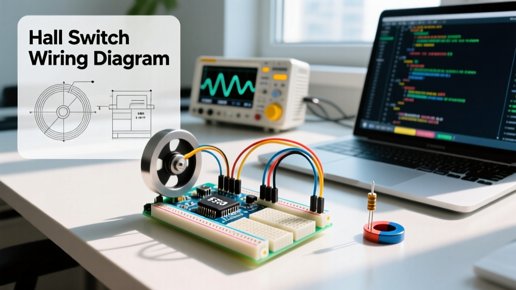

Mastering the Hall Switch Arduino Integration
When building projects that require non-contact position sensing, RPM counting, or limit switching, a hall switch Arduino setup is the gold standard. Unlike linear Hall sensors (such as the SS49E) that output an analog voltage proportional to magnetic flux density, digital Hall switches output a clean, discrete HIGH or LOW signal. This digital output is triggered when the perpendicular magnetic field (B-field) crosses a specific threshold, making them ideal for direct microcontroller interfacing.
However, transitioning from a basic breadboard prototype to a reliable, noise-immune deployment requires understanding magnetic hysteresis, open-drain architectures, and interrupt service routines (ISRs). This guide provides exact wiring schematics, production-grade C++ code, and troubleshooting frameworks for real-world maker and industrial applications.
Sensor Selection Matrix: 2026 Component Landscape
Choosing the right Hall switch depends on your magnetic pole requirements and operating voltage. While the legacy Allegro A3144 remains popular in hobbyist kits, modern alternatives like the Texas Instruments DRV5013 offer superior thermal stability and lower voltage operation for 3.3V microcontrollers. Below is a comparison of the three most common digital Hall switches available on platforms like DigiKey and Mouser.
| Model | Type | Operate Point (B_op) | Release Point (B_rp) | VCC Range | Approx. Price (2026) |
|---|---|---|---|---|---|
| A3144E | Unipolar (South) | 3.5 mT (typ) | 1.5 mT (typ) | 4.5V - 24V | $0.12 (Clone) / $0.65 (OEM) |
| DRV5013 | Unipolar (Omni) | 2.1 mT (typ) | 1.2 mT (typ) | 2.5V - 5.5V | $0.32 |
| US1881 | Bipolar Latch | 3.0 mT (South) | -3.0 mT (North) | 3.5V - 24V | $0.25 |
Expert Note: Unipolar switches (A3144, DRV5013) activate with one magnetic pole (usually South) and release when the magnet is removed. Bipolar latches (US1881) require the opposite pole (North) to release the switch, making them perfect for rotational RPM counting where alternating N-S poles on a ring magnet pass by the sensor.
Bulletproof Hardware Wiring
The most common point of failure in a hall switch Arduino circuit is ignoring the open-drain output architecture. Digital Hall switches do not actively drive the output pin HIGH. Instead, they pull the output to GND (LOW) when the magnetic threshold is met. When the magnet is removed, the output floats.
The Mandatory Pull-Up Resistor
You must use a pull-up resistor to define the HIGH state. While the Arduino Uno (ATmega328P) has internal pull-ups (~20kΩ to 50kΩ), they are often too weak to overcome electromagnetic interference (EMI) in noisy environments. Use an external 4.7kΩ or 10kΩ resistor tied between the sensor's output pin and VCC (5V or 3.3V, matching your MCU logic level).
Decoupling and EMI Suppression
Hall switches are frequently mounted near brushed DC motors or stepper drivers, which generate massive voltage spikes and high-frequency noise. The internal Schmitt trigger of the sensor can false-trigger from this EMI.
Hardware Rule of Thumb: Always place a 100nF (0.1µF) X7R ceramic bypass capacitor directly across the VCC and GND pins of the Hall sensor. For maximum noise immunity, this capacitor must be physically located within 5mm of the sensor body, not back at the Arduino power rails.
Wiring Pinout (A3144 / DRV5013 TO-92 Package)
- Pin 1 (VCC): Connect to Arduino 5V (or 3.3V for DRV5013).
- Pin 2 (GND): Connect to Arduino GND.
- Pin 3 (OUT): Connect to Arduino Digital Pin 2 (Interrupt capable). Add 10kΩ pull-up to VCC.
Arduino Code: Interrupt-Driven RPM Counting
Polling a Hall switch using digitalRead() inside the loop() function is acceptable for slow-moving door alarms. However, for motor RPM counting or high-speed encoder emulation, polling will miss pulses. You must use hardware interrupts. The Arduino attachInterrupt() documentation outlines how to map hardware interrupt vectors to specific pins.
Below is a production-ready sketch that calculates RPM using a unipolar Hall switch and a single neodymium magnet mounted on a rotating shaft.
// Hall Switch Arduino RPM Counter
// Target: Arduino Uno / Nano (ATmega328P)

const byte HALL_PIN = 2; // Hardware interrupt 0 on Uno/Nano
const byte MAGNET_COUNT = 1; // Number of magnets on the shaft
const unsigned long DEBOUNCE_MS = 5; // Mechanical bounce / EMI filter time

volatile unsigned long lastPulseMicros = 0;
volatile unsigned long pulseIntervalMicros = 0;
volatile bool newPulseAvailable = false;

void setup() {
  Serial.begin(115200);
  // External 10k pull-up recommended, but internal enabled as fallback
  pinMode(HALL_PIN, INPUT_PULLUP);

  // Attach interrupt on FALLING edge (sensor pulls to GND when triggered)
  attachInterrupt(digitalPinToInterrupt(HALL_PIN), hallISR, FALLING);
}

void hallISR() {
  unsigned long currentMicros = micros();
  // Software debounce to prevent EMI double-triggering
  if (currentMicros - lastPulseMicros > (DEBOUNCE_MS * 1000)) {
    pulseIntervalMicros = currentMicros - lastPulseMicros;
    lastPulseMicros = currentMicros;
    newPulseAvailable = true;
  }
}

void loop() {
  if (newPulseAvailable) {
    // Disable interrupts briefly to safely read 32-bit volatile variable
    noInterrupts();
    unsigned long intervalCopy = pulseIntervalMicros;
    newPulseAvailable = false;
    interrupts();

    if (intervalCopy > 0) {
      // Calculate RPM: (60 seconds * 1,000,000 microseconds) / (interval * magnets)
      float rpm = 60000000.0 / (float)(intervalCopy * MAGNET_COUNT);
      Serial.print("Calculated RPM: ");
      Serial.println(rpm, 1);
    }
  }

  // Handle stalled motor (no pulse for > 1 second)
  noInterrupts();
  unsigned long lastCopy = lastPulseMicros;
  interrupts();

  if (micros() - lastCopy > 1000000 && pulseIntervalMicros != 0) {
    Serial.println("Calculated RPM: 0.0 (Stalled)");
    pulseIntervalMicros = 0; // Reset to prevent repeating
  }
}
Code Architecture Breakdown
- Volatile Variables: Any variable modified inside the ISR (
hallISR) and read in the main loop must be declaredvolatile. This prevents the compiler from caching the variable in a CPU register, ensuring the main loop always reads the latest memory value. - Atomic Reads: The ATmega328P is an 8-bit microcontroller. Reading a 32-bit
unsigned longtakes multiple clock cycles. If an interrupt fires mid-read, the variable will be corrupted. We usenoInterrupts()andinterrupts()to create a safe atomic copy. - Software Debounce: While Hall sensors are solid-state and lack physical switch bounce, the circuit can experience EMI bounce. The
DEBOUNCE_MScheck ignores any secondary triggers that occur within 5 milliseconds of the primary edge.
Real-World Troubleshooting & Failure Modes
Even with perfect code, physical deployment introduces variables that break basic prototypes. Here is how to diagnose the most common hall switch Arduino anomalies.
1. Phantom Triggers Near DC Motors
Symptom: RPM readings are erratic or double the expected value when the sensor is mounted near a brushed motor.
Cause: Brushed motors emit broad-spectrum EMI. The long wires running from the sensor to the Arduino act as antennas, inducing voltage spikes that cross the Schmitt trigger threshold.
Solution: Use twisted-pair wire for the sensor connection. Add a hardware RC low-pass filter (e.g., 100Ω series resistor on the signal line + 1nF capacitor to GND at the Arduino pin) to filter out high-frequency noise before it reaches the microcontroller.
2. Sensor Never Triggers (Stuck HIGH)
Symptom: The serial monitor shows no RPM, and a multimeter reads a constant 5V on the output pin regardless of magnet proximity.
Cause: Incorrect magnet polarity. Unipolar switches like the A3144 are highly sensitive to the South pole. If you are presenting the North pole, the B-field threshold will never be met.
Solution: Flip the neodymium magnet. If using a bipolar latch (US1881), ensure the magnetic field is strong enough to cross both the operate and release thresholds (typically requiring a minimum of 5mT flux density at the sensor face).
3. RPM Drops to Zero at High Speeds
Symptom: Accurate readings at low speeds, but the system registers 0 RPM or completely stalls when the motor exceeds 5,000 RPM.
Cause: The sensor's output transistor cannot switch fast enough, or the magnet is moving too fast for the sensor's internal sampling bandwidth (typically 2kHz to 10kHz for standard Hall ICs).
Solution: Upgrade to a high-bandwidth sensor like the TI DRV5055 (if analog is acceptable) or a high-speed digital switch with a 20kHz+ sampling rate. Alternatively, reduce the serial baud rate or move the Serial.print() function to a timed interval rather than printing on every single pulse.
Summary
Integrating a hall switch Arduino setup goes far beyond connecting three wires. By selecting the correct magnetic topology (unipolar vs. bipolar), implementing proper open-drain pull-ups, and utilizing hardware interrupts with atomic variable reads, you can build industrial-grade RPM counters and limit switches. Always prioritize physical EMI mitigation at the hardware level—software debouncing can only do so much against the raw electrical noise of high-power motors.