
The Reality of Arduino Image Corruption in Modern MCU Development
When embedded engineers and advanced makers refer to an 'Arduino image' in 2026, they are rarely talking about a JPEG or a pinout diagram. In the context of advanced microcontroller units (MCUs) like the ESP32-S3, Raspberry Pi Pico (RP2040), and the Arduino Portenta H7, an 'image' refers to the compiled firmware binary, the bootloader payload, or the disk image flashed to the device's non-volatile memory. Diagnosing Arduino image flash errors is one of the most critical troubleshooting skills in modern hardware development. A corrupted binary, a mismatched partition table, or a failed USB Device Firmware Upgrade (DFU) handshake can instantly turn a $30 development board into a seemingly bricked paperweight.
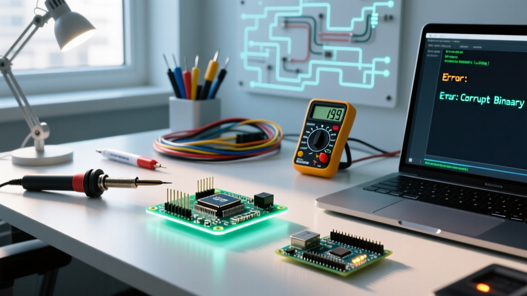
Unlike the legacy ATmega328P days where a simple avrdude hex upload either worked or failed outright, modern 32-bit architectures utilize complex bootloaders, multi-stage boot sequences, and external SPI flash chips. When an Arduino image fails to boot, the Serial Monitor often spits out cryptic hex addresses, checksum failures, or watchdog timer (WDT) reset loops. This guide provides a deep-dive diagnostic framework for identifying, isolating, and resolving firmware image errors across the most popular advanced Arduino-compatible ecosystems.
The Anatomy of an Arduino Firmware Image
Before diagnosing a failure, you must understand what the MCU is actually trying to execute. A complete Arduino firmware deployment is rarely a single monolithic file. It is typically an 'image' composed of distinct memory regions:
- The Bootloader Image: A small, protected binary (often residing in the first 4KB to 16KB of flash) that initializes the hardware clocks and checks for upload requests before handing execution to the main app.
- The Partition Table / Filesystem: Crucial for ESP32 and RP2040 boards, this defines where the application image starts, where the SPIFFS/LittleFS data resides, and where Over-The-Air (OTA) update slots are located.
- The Application Image: Your actual compiled Arduino sketch (the
.bin,.hex, or.uf2file) containing thesetup()andloop()logic.
When an 'Invalid Image' error occurs, it means the hardware's ROM bootloader or the secondary bootloader has inspected the application image header, found a mismatch in the expected checksum, or encountered an invalid memory boundary, and has halted execution to prevent hardware damage.
Diagnostic Matrix: Top Arduino Image Flash & Boot Errors
The following table maps common serial output errors to their underlying root causes and the specific diagnostic tools required to verify the image integrity.
| Error Signature (Serial Output) | Target MCU | Root Cause Analysis | Diagnostic / Recovery Tool |
|---|---|---|---|
rst:0x10 (RTCWDT_RTC_RESET) |
ESP32 / ESP32-S3 | Application image is corrupt or missing; hardware watchdog triggered during boot handshake. | esptool.py flash_id & read_flash |
Invalid image size / Bad checksum |
ESP32 Family | Partition table offset mismatch; image flashed to 0x0 instead of 0x1000 (or vice versa). | Arduino IDE Partition CSV editor |
| Drive disappears mid-transfer | RP2040 (Pico) | UF2 image block header corrupted; USB mass storage stack crashed due to bad flash sector. | picotool info & picotool verify |
DFU state error / Poll timeout |
Portenta H7 (STM32) | DFU alternate setting mismatch; bootloader expects different image alignment or encryption. | dfu-util -l & STM32CubeProgrammer |
1. ESP32-S3: Diagnosing 'Invalid Image Size' and SPI Flash Mode Clashes
The ESP32 family relies heavily on external SPI flash chips (typically 8MB or 16MB Winbond or Macronix modules). A highly prevalent Arduino image error on the ESP32-S3 occurs when the compiled binary assumes a Quad I/O (QIO) flash mode, but the physical hardware or the bootloader is configured for Dual I/O (DIO). When the ROM bootloader attempts to read the image header using the wrong SPI bus width, it reads garbage data, resulting in an immediate Invalid image size or checksum failed panic.
The Fix: You must force the flash mode at the compiler level and verify the physical chip capabilities. In the Arduino IDE 2.x, navigate to Tools > Flash Mode and explicitly select DIO if you are using third-party clone boards, as many budget manufacturers substitute QIO chips with DIO equivalents. If the board is already in a bootloop, you cannot rely on the Arduino IDE's serial uploader. You must use the command-line Espressif esptool to wipe the flash and force the correct parameters:
esptool.py --chip esp32s3 --port /dev/ttyACM0 erase_flash
esptool.py --chip esp32s3 --port /dev/ttyACM0 write_flash -z 0x0 bootloader.bin 0x8000 partition-table.bin 0x10000 firmware.bin
By explicitly defining the hex offsets (0x0 for bootloader, 0x8000 for partitions, 0x10000 for the app image), you bypass the Arduino IDE's automated wrapper and guarantee the image lands in the correct memory sector.
2. RP2040 (Pico): UF2 Image Rejection and the 'Disappearing Drive' Phenomenon
The Raspberry Pi RP2040, widely used in the Arduino Nano RP2040 Connect and generic Pico boards, utilizes the USB Flashing Format (UF2). A UF2 file is essentially a wrapper that packages the binary payload into 512-byte blocks, each containing a 32-byte header with metadata like the target flash address and a magic number. According to the official Microsoft UF2 Specification, if the RP2040's internal USB bootloader detects a malformed header or an out-of-bounds target address, it will silently reject the block.
The Diagnostic Scenario: You drag and drop a 2MB .uf2 Arduino image onto the RPI-RP2 drive. The progress bar reaches 99%, the drive abruptly unmounts, but when the board reboots, it runs the old firmware or enters a continuous reset loop. This indicates that the final blocks of the image were written to a degraded flash sector, or the file system cache on your host OS truncated the file before the USB stack could finalize the write.
The Fix: Never trust the host OS drag-and-drop GUI for critical deployments. Use the official picotool via the command line to verify the image integrity post-flash. Connect the board while holding the BOOTSEL button, then run:
picotool load -v firmware.uf2
picotool verify
The -v flag forces a block-by-block readback verification, ensuring the silicon actually holds the exact Arduino image you intended to flash.
3. Arduino Portenta H7: DFU Image Upload Timeouts and Bootloader Bricking
The Arduino Portenta H7 features a powerful dual-core STM32H747XI MCU. Flashing an image to this board relies on the STM32 DFU (Device Firmware Upgrade) protocol. A catastrophic error unique to the Portenta ecosystem occurs when a user attempts to flash an M4-core image to the M7-core memory address space (or vice versa), or when the DFU Alternate Setting is incorrectly targeted.
When this happens, the dfu-util process will hang indefinitely at 'Poll timeout', and the board's RGB LED will pulse a frantic red, indicating the bootloader has locked out the USB interface to protect the core memory. To diagnose this, you must query the DFU interface directly to see what memory boundaries the bootloader is currently exposing:
dfu-util -lThis command will list the available Alternate Settings (e.g., alt=0 for M7, alt=1 for M4). If your Arduino IDE is attempting to push the image to alt=0 but the board is stuck in an M4 recovery state, the upload will fail. The recovery protocol requires using the STM32CubeProgrammer to manually connect via UART (using the Portenta's breakout board RX/TX pins) and flash the official Arduino bootloader recovery image to reset the DFU state machine.
Step-by-Step Recovery: Unbricking a Corrupted Image via Hardware Handshake
When software resets fail and the MCU's primary bootloader is corrupted, you must force the silicon into its mask-ROM recovery mode. This requires precise hardware timing.
- Identify the Boot Pins: On the ESP32-S3, this is GPIO0. On the RP2040, it is the BOOTSEL button (which internally pulls the QSPI CS pin low). On the Portenta H7, it is the BOOT0 pin on the high-density connector.
- Execute the Timing Sequence: Pull the Boot pin to GND. Press and release the RESET button. Wait exactly 100 milliseconds, then release the Boot pin from GND. This 100ms window is critical; releasing it too early allows the application image to hijack the boot sequence, while holding it too long on some STM32 chips disables the internal flash controller.
- Verify the ROM Handshake: Open your serial terminal at 115200 baud. You should see a static MAC address or a 'Waiting for download' string. This confirms the mask-ROM is active and ready to accept a fresh bootloader image.
- Flash the Bootloader First: Never flash the application image directly to a bricked board. Always flash the manufacturer's default bootloader
.binto the 0x0 address first, reset the board, and then use the Arduino IDE to upload your sketch normally.
Expert Insight on Flash Wear: Repeatedly flashing full Arduino images to the same memory sector during rapid prototyping can cause localized wear-out on the SPI flash chip's oxide layer, leading to 'stuck bits' that cause silent image corruption. In 2026, best practice dictates using the 'Erase All Flash Before Sketch Upload' option in the Arduino IDE only when changing partition schemes. For iterative code changes, rely on the bootloader's differential page-erase algorithms to prolong the lifespan of your development hardware.
Preventative Measures for Custom Image Deployment
To prevent Arduino image errors from reaching the hardware level, implement these validation steps in your CI/CD pipeline or local build process:
- Enable CRC32 Verification: For ESP32 projects, add
CONFIG_APP_ROLLBACK_ENABLEandCONFIG_BOOTLOADER_APP_ROLLBACK_ENABLEin yoursdkconfigfile. This forces the bootloader to verify the CRC32 checksum of the application image header before execution, gracefully falling back to an OTA partition if the primary image is corrupt. - Monitor Binary Bloat: A common cause of 'Image too large' errors is the silent inclusion of debug libraries. Use the
arm-none-eabi-sizetool on your compiled.elffile to inspect the exact RAM and Flash footprint before generating the final binary. - Lock the Bootloader Region: Use the MCU's hardware Write Protection (WP) registers to lock the first 16KB of flash. This ensures that a rogue pointer or buffer overflow in your Arduino sketch can never overwrite the bootloader image, guaranteeing you will always have a way to recover the board via USB.
By shifting your perspective from 'uploading a sketch' to 'deploying and verifying a firmware image,' you align your workflow with professional embedded systems engineering, drastically reducing the time spent diagnosing cryptic bootloops and hardware panics.