
Decoding the 'Arduino MAX' Search Intent
When electrical engineers and makers search for Arduino MAX, they are generally referring to one of two distinct concepts: the maximum I/O pin-count board (the Arduino Mega 2560) or the integration of Maxim Integrated’s (now Analog Devices) legendary MAX-series ICs. In the realm of component-level configuration, the latter is vastly more common. Specifically, the MAX7219 and MAX7221 LED display drivers are foundational to thousands of DIY projects, from scrolling marquees to complex 7-segment instrument clusters.
This comprehensive 2026 configuration guide bypasses the superficial tutorials and dives deep into the hardware realities, SPI protocol nuances, and power delivery requirements needed to successfully configure an Arduino with MAX7219 LED matrices and 7-segment displays.
Hardware Architecture: MAX7219 vs. MAX7221
Before writing a single line of code, you must understand the silicon you are driving. While often sold interchangeably on generic FC-119 LED matrix modules, the MAX7219 and MAX7221 have distinct SPI behaviors that will cause communication failures if misconfigured in your Arduino sketch.
- MAX7219: Tolerates standard SPI Mode 0 and Mode 3. It does not strictly enforce the SPI chip-select (CS) line to be active-low for data shifting, making it forgiving on bit-banged software SPI implementations.
- MAX7221: Strictly requires SPI Mode 0 (CPOL=0, CPHA=0). Furthermore, the MAX7221 features high-impedance outputs when the CS pin is high, making it the mandatory choice if you are sharing the SPI bus with other peripherals like SD cards or RF modules.
The Critical R_SET Calculation
The most frequent point of failure in custom MAX7219 PCB designs is an incorrectly calculated current-limiting resistor ($R_{SET}$). The MAX7219 uses a single external resistor connected between the $V_{CC}$ and $I_{SET}$ pins to dictate the peak segment current. The internal current regulator multiplies this reference current by approximately 100.
According to the Analog Devices MAX7219 Datasheet, the formula is:
Formula: $R_{SET} = \frac{V_{F} \times 40}{I_{SEG}}$
Where $V_{F}$ is the LED forward voltage and $I_{SEG}$ is the desired segment current.
R_SET Reference Table for Common LED Types
| LED Color / Type | Forward Voltage ($V_F$) | Target Current ($I_{SEG}$) | Required $R_{SET}$ Value |
|---|---|---|---|
| Standard Red | 2.0V | 20 mA | 40.0 kΩ |
| Standard Green | 2.2V | 20 mA | 44.0 kΩ |
| Standard Blue / White | 3.2V | 20 mA | 64.0 kΩ |
| High-Brightness White | 3.4V | 10 mA | 136.0 kΩ |
Note: Never use an $R_{SET}$ value lower than 10 kΩ, as this will exceed the absolute maximum current rating of the internal driver transistors, leading to immediate thermal shutdown or silicon degradation.
SPI Wiring and Pin Mapping
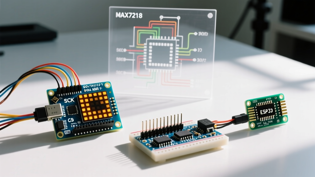
The MAX7219 utilizes a simplified 3-wire SPI interface. Below is the standard hardware SPI mapping for the most common microcontrollers used in 2026.
| MAX7219 Pin | Arduino Uno / Nano (ATmega328P) | Arduino Mega 2560 | ESP32 (DevKit V1) | Signal Function |
|---|---|---|---|---|
| VCC | 5V | 5V | 5V (VIN or 5V pin) | Power Supply (4.0V - 5.5V) |
| GND | GND | GND | GND | Logic & Power Ground |
| DIN | Pin 11 (MOSI) | Pin 51 (MOSI) | Pin 23 (MOSI) | Serial Data In |
| CS (LOAD) | Pin 10 (SS) | Pin 53 (SS) | Pin 5 (Custom SS) | Chip Select (Active Low) |
| CLK | Pin 13 (SCK) | Pin 52 (SCK) | Pin 18 (SCK) | Serial Clock |
Power Delivery: The Hidden Bottleneck
A standard 8x8 LED matrix module contains 64 LEDs. If all LEDs are illuminated simultaneously at 20mA, a single module will draw 1.28 Amps. The MAX7219 multiplexes the display, meaning only one row (8 LEDs) is active at any given microsecond, reducing the average current draw to roughly 320mA per module at maximum intensity. However, transient current spikes during row-switching can cause severe voltage droop.
The Decoupling Mandate
Generic, mass-produced FC-119 modules often ship with a marginal 0.1µF ceramic capacitor. For stable operation, especially when daisy-chaining more than three modules, you must implement the following power configuration:
- Local Decoupling: Solder a 0.1µF ceramic capacitor and a 10µF electrolytic capacitor directly across the VCC and GND pins on the first module in the chain.
- Bulk Capacitance: If chaining 4 to 8 modules, add a 100µF to 470µF electrolytic capacitor at the power injection point.
- Power Injection: Do not rely on the Arduino's onboard 5V linear regulator to power the matrices. Inject 5V from a dedicated buck converter (e.g., LM2596 or MP1584EN) directly into the module chain's VCC rail, sharing only the GND with the Arduino.
Software Configuration: Choosing the Right Library
While the legacy LedControl library is frequently cited in outdated tutorials, it is fundamentally unsuited for modern, complex projects. It relies on software bit-banging (blocking the CPU) and limits you to 8 devices.
For professional-grade configurations in 2026, the MD_MAX72XX library by MajicDesigns is the industry standard. It leverages hardware SPI, supports non-blocking animations, and can address up to 255 cascaded devices.
Initialization Code Snippet (Hardware SPI)
#include <MD_MAX72xx.h>
#include <SPI.h>

#define HARDWARE_TYPE MD_MAX72XX::FC16_HW
#define MAX_DEVICES 4
#define CS_PIN 10

MD_MAX72XX mx = MD_MAX72XX(HARDWARE_TYPE, CS_PIN, MAX_DEVICES);

void setup() {
  SPI.begin();
  mx.begin();
  mx.control(MD_MAX72XX::INTENSITY, 5); // Set intensity 0-15
  mx.control(MD_MAX72XX::UPDATE, MD_MAX72XX::ON);
  mx.clear();
}
Crucial Detail: Ensure the HARDWARE_TYPE macro matches your physical module. FC-16 modules (common in 4-in-1 matrix blocks) wire the matrices differently than generic Parola or ICStation modules. Selecting the wrong type will result in scrambled, mirrored, or inverted text.
Daisy-Chaining Mechanics and Signal Integrity
The MAX7219 features a DOUT (Data Out) pin that shifts the 16-bit data stream to the next chip's DIN. While theoretically infinite, practical daisy-chaining hits a wall around 8 to 12 modules due to signal degradation and propagation delay.
Mitigating Signal Degradation
- Wire Length: Keep the ribbon cables between modules under 15cm. Longer runs act as antennas, picking up EMI and corrupting the CLK signal.
- Level Shifting: If you are driving a MAX7219 chain with a 3.3V microcontroller (like the ESP32 or Raspberry Pi Pico), the MAX7219's $V_{IH}$ (High-Level Input Voltage) requires a minimum of 3.5V when operating on a 5V rail. You must use a logic level shifter (e.g., 74AHCT125) on the DIN, CS, and CLK lines to prevent ghosting and random pixel flickering.
Troubleshooting Edge Cases
Even with perfect wiring, edge cases arise. Here is how to diagnose the most common MAX7219 anomalies:
- Ghosting / Faint Pixels: Usually caused by a missing or insufficient pull-up resistor on the CS line, or driving a 5V MAX7219 with 3.3V logic without a level shifter. The chip misinterprets noise as clock pulses.
- Random Full-Module Illumination: This indicates a brownout. The internal logic state machine has crashed due to a voltage droop. Verify your bulk capacitance and ensure your power supply can deliver at least 1A per 4 modules.
- Asynchronous Scrolling (Tearing): Occurs when the SPI clock speed is set too high for the physical wire length. In the Arduino SPI Reference, you can adjust the clock divider. Drop the SPI clock from 8MHz down to 2MHz or 1MHz if operating long chains.
Summary
Configuring an Arduino with MAX-series ICs like the MAX7219 requires moving beyond simple plug-and-play assumptions. By calculating the exact $R_{SET}$ value for your specific LED chemistry, implementing rigorous power decoupling, utilizing hardware SPI via modern libraries like MD_MAX72XX, and respecting logic-level thresholds, you transform a flickering, unreliable toy into a robust, commercial-grade display system.