
"A switch doesn't just close; it chatters, bounces, and rings. Treating it as a simple digital transition is the hallmark of a prototype, not a production system." — Embedded Systems Design Principle
As of 2026, with modern maker microcontrollers like the RP2350 and ESP32-S3 operating at clock speeds exceeding 150MHz, relying on blocking delays for input handling wastes millions of CPU cycles. If you are migrating a legacy project from a breadboard prototype to a robust, production-ready enclosure, arduino button debouncing must evolve from a naive delay(50) hack to a deterministic, non-blocking architecture. This migration guide details how to upgrade your firmware and hardware to eliminate phantom triggers, reduce latency, and ensure industrial-grade reliability.
The Hidden Cost of Naive Debouncing
Most beginners start with the standard Arduino built-in debounce tutorial, which relies on tracking millis() and blocking state changes. While better than a raw delay(), legacy state-tracking code often becomes a tangled web of global variables (lastDebounceTime, lastButtonState, buttonState) that fails when scaling to multiple inputs.
When mechanical contacts close, the physical metal reeds vibrate. According to Jack Ganssle's definitive guide on switch debouncing, a typical tactile switch can bounce anywhere from 1 to 15 milliseconds. If your firmware polls the pin during this window without a proper state machine, a single button press can register as a dozen distinct interrupts, causing erratic menu navigation or accidental machine actuation.
Migration Path 1: Refactoring to the Bounce2 State Machine
The most efficient software migration is abandoning manual millis() tracking in favor of the Bounce2 library repository. Bounce2 encapsulates the debouncing logic into an object-oriented state machine, freeing your main loop from timing clutter.
Legacy Code vs. Bounce2 Implementation
In a legacy sketch, handling three buttons requires nine separate global variables and a massive, repetitive if/else block in the loop. By migrating to Bounce2, you instantiate objects and rely on edge-detection methods.
// Modern Bounce2 Migration Pattern
#include

Bounce modeBtn = Bounce();
Bounce startBtn = Bounce();

void setup() {
  // Attach pins with internal pull-ups and set 10ms debounce interval
  modeBtn.attach(2, INPUT_PULLUP);
  modeBtn.interval(10);
  startBtn.attach(3, INPUT_PULLUP);
  startBtn.interval(10);
}

void loop() {
  modeBtn.update();
  startBtn.update();

  // Non-blocking edge detection
  if (modeBtn.fell()) {
    triggerModeChange();
  }
  if (startBtn.rose()) {
    activateMotor();
  }
}
Expert Insight: Always use .fell() (transition from HIGH to LOW) for active-low switches wired to ground. This ensures your logic triggers exactly once on the physical press, ignoring the release bounce entirely.
Migration Path 2: Hardware Upgrades for Hostile Environments
Software debouncing is sufficient for clean, short-trace PCB environments. However, if you are upgrading a project to operate in an electrically noisy environment (e.g., near stepper motors, relays, or VFDs), electromagnetic interference (EMI) can induce voltage spikes that mimic switch bounces. You must migrate to a hardware debouncing topology.
The RC Filter + Schmitt Trigger Topology
A simple capacitor across the switch pins will filter high-frequency noise, but it creates a slow voltage ramp that can cause the microcontroller's digital input buffer to oscillate violently as it crosses the logic threshold. The professional upgrade is pairing an RC low-pass filter with a Schmitt trigger IC, such as the SN74HC14 or CD40106.
- Resistor (R1): 10kΩ pull-up resistor.
- Capacitor (C1): 100nF (0.1µF) X7R ceramic capacitor to ground.
- Time Constant (τ): τ = R × C = 10,000 × 0.0000001 = 1 millisecond.
- Schmitt Trigger: SN74HC14 hex inverter (Costs approximately $0.45 per IC in 2026). The hysteresis gap (typically 0.9V to 1.6V on a 5V supply) prevents output oscillation during the capacitor's charge curve.
Strategy Comparison Matrix
Use the following matrix to determine which debouncing migration path fits your specific project constraints.
| Strategy | CPU Overhead | Latency | Hardware Cost (per unit) | Best Use Case |
|---|---|---|---|---|
Naive delay() |
100% (Blocking) | 50ms+ | $0.00 | Throwaway classroom prototypes |
Manual millis() Tracking |
Low | 10-20ms | $0.00 | Simple 1-button legacy projects |
| Bounce2 Library (Software) | Minimal (Non-blocking) | 5-15ms | $0.00 | Consumer UIs, multi-button panels |
| RC Filter + Schmitt Trigger | Zero (Hardware handled) | ~3ms | ~$0.60 | Noisy environments, long cable runs |
| FreeRTOS Task / Semaphore | Isolated Core | 1ms polling | $0.00 | ESP32/STM32 real-time industrial systems |
Advanced Edge Cases: Industrial and Reed Switches
Not all switches are created equal. When migrating hardware, you must tune your debounce intervals to the physical characteristics of the specific switch model:
- Standard Tactile Switches (e.g., Omron B3F series): Typically exhibit 2ms to 5ms of bounce. A 10ms software interval in Bounce2 is perfectly adequate.
- Cherry MX Mechanical Keyswitches: Can bounce for 5ms to 12ms. Set your interval to 15ms to prevent double-typing in macro pads.
- Magnetic Reed Switches: Often suffer from severe contact flutter lasting 10ms to 20ms due to the flexibility of the glass-encased reeds. Increase software intervals to 25ms or add a 220nF hardware capacitor.
- Industrial Limit Switches (e.g., Honeywell GLS series): Heavy-duty snap-action switches can generate massive contact arcing and bounce for up to 50ms. These require hardware RC filtering combined with opto-isolators to protect the microcontroller from inductive kickback.
Step-by-Step Migration Workflow
Follow this checklist to safely upgrade your legacy Arduino sketches without introducing regressions:
- Audit Existing Inputs: Identify every
digitalRead()tied to a mechanical switch or relay contact. - Strip Blocking Delays: Remove all
delay()calls used for debouncing. Replace them with non-blocking timing logic. - Implement Bounce2 Objects: Instantiate a
Bounceobject for each input in the global scope. - Configure Pull-ups: Use the
INPUT_PULLUPmode in theattach()method to eliminate the need for external 10kΩ resistors on the PCB, saving board space and BOM costs. - Set Appropriate Intervals: Use
.interval(10)for standard UI buttons, and.interval(30)for heavy mechanical relays or reed switches. - Refactor Logic to Edge Detection: Replace
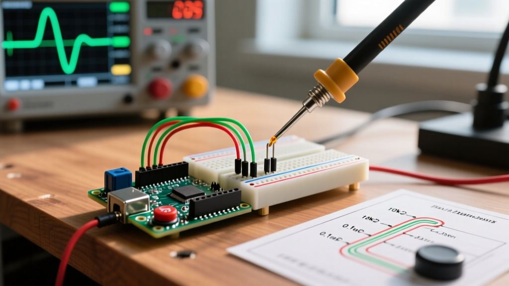
if (digitalRead(pin) == LOW)withif (btn.fell())to ensure the action fires exactly once per physical actuation. - Oscilloscope Validation: If operating in a high-EMI environment, probe the GPIO pin with an oscilloscope to verify that voltage spikes do not exceed the logic threshold before the software polling window catches them.
By migrating away from naive delays and embracing dedicated state machines or hardware hysteresis, your projects will achieve the responsiveness and reliability expected of modern commercial electronics. Whether you are building a custom macro keyboard or an industrial motor controller, proper debouncing is the foundation of deterministic embedded design.