
Why the Automotive Electrical Environment is Hostile
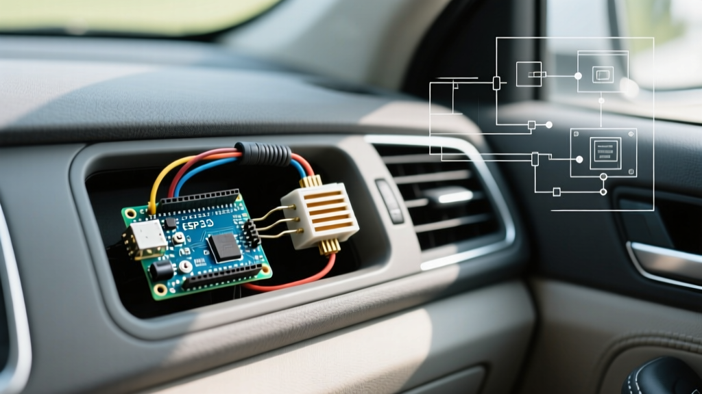
Installing an Arduino in a car opens up incredible possibilities, from custom OBD2 telemetry dashboards to automated lighting and active suspension logging. However, the automotive electrical environment is notoriously hostile to microcontrollers. While a car battery is nominally 12V, the actual system voltage fluctuates wildly. When the engine is running, the alternator pushes the system to 13.8V–14.4V. During a cold crank, voltage can sag below 6V, causing brownouts. More dangerously, a 'load dump'—which occurs when the battery is disconnected while the alternator is charging—can send voltage spikes exceeding 40V through the wiring harness.
According to the ISO 16750-2 standard for automotive electrical loads, any electronics connected to a vehicle must survive these severe transient pulses. If you simply plug your Arduino into a cheap 12V-to-USB cigarette lighter adapter, you are risking catastrophic failure of the microcontroller's voltage regulator and GPIO pins. This tutorial provides a professional-grade, step-by-step framework for safely powering and wiring an Arduino in a vehicle.
Critical Warning: Never rely on the onboard AMS1117-5.0 linear regulator found on standard Arduino Uno or Nano clones for automotive power. Dropping 14V to 5V linearly generates immense heat (roughly 0.9W at just 100mA), which will trigger thermal shutdown and cause your sketch to randomly crash while driving.
Phase 1: Designing a Bulletproof 12V to 5V Power Supply
To run an Arduino reliably in a vehicle, you must use a switching DC-DC buck converter. Switching regulators efficiently step down the voltage by rapidly switching the input on and off, dissipating very little heat compared to linear regulators. When selecting a buck converter for automotive use, you must ensure it can handle a maximum input voltage of at least 40V to survive load dump events.
Power Supply Options Comparison
| Component / Module | Topology | Max Input Voltage | Cost (Approx.) | Verdict |
|---|---|---|---|---|
| Onboard AMS1117 (Arduino) | Linear | 15V (Absolute Max) | $0 (Included) | DO NOT USE. Overheats and fails. |
| LM2596HV Module | Buck | 53V | $3.00 - $6.00 | Good for prototyping. Cheap clones often fail under vibration. |
| RECOM R-78E5.0-1.0 | Switching | 28V (Requires TVS) | $6.50 | Best for Production. Automotive-grade, SIP-3 package. |
| TI LM53635-Q1 | Synchronous Buck | 36V | $4.50 (IC only) | Excellent for custom PCB designs. AEC-Q100 qualified. |
For most DIYers and makers building a permanent Arduino in a car setup, pairing a high-quality buck converter like the RECOM R-78E5.0-1.0 with a transient voltage suppression (TVS) diode is the most reliable and compact solution.
Phase 2: Circuit Protection and Noise Filtering
Modern vehicles, especially 2026-era mild-hybrids with 48V-to-12V DC-DC step-down modules, generate high-frequency switching noise on the 12V rail. To protect your microcontroller, you must build a front-end protection circuit before the power reaches your buck converter.
The Protection Circuit Bill of Materials (BOM)
- TVS Diode (SMAJ24A or SMAJ15A): Clamps voltage spikes to a safe level (e.g., 24V or 15V) during a load dump. Cost: ~$0.15.
- Automotive Fuse (ATO/ATC): A 1A or 2A blade fuse to protect against dead shorts. Cost: ~$1.00.
- Common Mode Choke (e.g., Bourns SRF0905A): Filters out high-frequency alternator whine and ignition EMI. Cost: ~$1.50.
- Decoupling Capacitors: A 100µF electrolytic capacitor (rated for 35V) and a 0.1µF ceramic capacitor placed as close to the buck converter input as possible.
Schematic Flow
12V Battery -> Fuse -> TVS Diode (Reverse Biased to Ground) -> Common Mode Choke -> Bulk Capacitor -> Buck Converter Input -> 5V to Arduino Vin
The TVS diode must be connected in reverse bias (cathode to 12V, anode to ground). Under normal operation, it acts as an open circuit. When a voltage spike exceeds its breakdown voltage, it conducts the excess energy to ground, saving your downstream components.
Phase 3: Step-by-Step Wiring and Installation
Proper physical installation is just as critical as the electrical design. High-vibration environments will quickly destroy soldered wire joints if not properly strain-relieved.
- Tap into the Fuse Box using an Add-a-Circuit: Do not splice into existing wires by piercing the insulation; this introduces corrosion points. Use an 'Add-a-circuit' (fuse tap) to draw power from an existing ignition-switched fuse slot. This ensures your Arduino turns on and off with the key, preventing parasitic battery drain.
- Use the Correct Wire Gauge: For a standard Arduino setup drawing under 500mA, 18 AWG stranded copper wire is ideal. It is thick enough to handle the current but flexible enough to route through the firewall.
- Establish a Star Ground: Never use the car's chassis as a return path for sensitive analog sensors. Run a dedicated 18 AWG ground wire directly from your circuit's common ground to a clean, unpainted metal bolt on the chassis. Use a star washer to bite through any remaining clear coat or oxidation, ensuring a milliohm-level resistance connection.
- Route Away from EMI Sources: Keep your Arduino wiring at least 6 inches away from ignition coil packs, spark plug wires, and the alternator. If you must cross a high-current wire, do so at a 90-degree angle to minimize inductive coupling.
- Secure and Strain-Relieve: Use TESA tape (automotive cloth tape) to bundle your wires. Avoid standard zip-ties for securing wires to moving components or sharp metal edges, as they will eventually cut through the insulation.
Phase 4: Interfacing with 12V Car Signals Safely
If your project involves reading 12V car signals (such as door switches, turn signals, or the reverse light circuit), you must never connect 12V directly to an Arduino GPIO pin. Doing so will instantly fry the ATmega328P's internal clamping diodes and destroy the microcontroller.
Method A: Optocouplers (Best for Digital Signals)
Use a PC817 optocoupler to provide complete galvanic isolation between the car's 12V system and the Arduino's 5V logic. Connect the 12V signal through a 1kΩ current-limiting resistor to the optocoupler's internal LED. On the Arduino side, connect the phototransistor output to a digital pin with the internal pull-up resistor enabled. This safely translates a 12V 'ON' signal to a 5V 'LOW' logic state.
Method B: Voltage Dividers (Best for Analog Signals)
If you need to read a variable 12V analog signal (like a fuel level sender), use a precision voltage divider. A 10kΩ and 4.7kΩ resistor pair will scale a 14.4V maximum input down to a safe 4.6V, well within the Arduino's 5V ADC range. Always add a 0.1µF capacitor across the lower resistor to filter out high-frequency noise before the signal reaches the analog pin.
Phase 5: CAN Bus Integration for Modern Vehicles
In modern vehicles, discrete 12V wires for accessories are disappearing, replaced by multiplexed CAN bus networks. To read engine RPM, coolant temperature, or steering angle, your Arduino must interface with the OBD2 CAN bus.
Use an MCP2515 CAN controller module paired with a TJA1050 transceiver. The TJA1050 handles the physical differential signaling (CAN_H and CAN_L) of the vehicle, while the MCP2515 translates those signals into SPI data that the Arduino can process. When wiring the OBD2 port (Standard J1962 connector), connect to Pin 6 (CAN High) and Pin 14 (CAN Low). Ensure your MCP2515 library is configured for the correct baud rate—typically 500 kbps for most modern powertrain networks.
For deeper insights into automotive network topologies, refer to Texas Instruments' Automotive Solutions documentation, which details the physical layer requirements for in-vehicle networking.
Troubleshooting Common Automotive MCU Failures
Even with careful planning, you may encounter issues. Here is how to diagnose the most common failure modes:
- Random Resets at Idle: Often caused by voltage sags when the radiator fan or fuel pump kicks on. Fix: Increase the bulk capacitance on your 5V rail by adding a 470µF capacitor directly across the Arduino's 5V and GND pins.
- ADC Readings are Erratic: Alternator whine is coupling into your analog ground. Fix: Implement a software low-pass filter (Exponential Moving Average) in your sketch, and ensure your analog sensors use a dedicated 'clean' ground trace back to the buck converter, separate from high-current digital grounds.
- Sketch Freezes After Engine Start: The massive current draw of the starter motor causes a severe brownout, corrupting the MCU's program counter. Fix: Add a hardware watchdog timer (WDT) to your Arduino sketch to automatically reset the board if it hangs for more than 2 seconds, and enable the Arduino's Brown-Out Detection (BOD) fuse via the IDE to prevent execution during low-voltage states.
Conclusion
Successfully deploying an Arduino in a car requires respecting the harsh realities of automotive electrical systems. By abandoning linear regulators in favor of automotive-grade buck converters, implementing TVS diode protection against load dumps, and isolating your GPIO pins from 12V signals, you can build a rock-solid vehicle interface. Whether you are logging lap times via CAN bus or building a custom telemetry display, these hardware foundations will ensure your project survives the road.