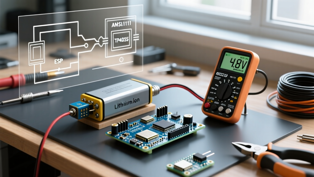

The 9V Alkaline Trap: Linear Regulator Inefficiency
When makers first explore off-grid projects, the most common battery for Arduino setups involve a standard 9V alkaline battery plugged directly into the barrel jack. While this works for a quick breadboard test, it is a catastrophic choice for any deployed, battery-powered project. Understanding why this fails requires looking at the onboard voltage regulation circuitry.
Diagnosis: Hot Voltage Regulators and Short Lifespans
The Arduino Uno and Nano route the barrel jack input through a linear voltage regulator—typically an NCP1117ST50T3G on genuine boards, or a cheaper AMS1117-5.0 on third-party clones. Linear regulators operate by burning excess voltage as heat. If you supply 9V and the board needs 5V, the regulator must drop 4V.
The efficiency of this conversion is simply V_out / V_in. In this case, 5V / 9V equals roughly 55% efficiency. A standard 9V alkaline battery has a usable capacity of about 400mAh. Because of the 55% efficiency and the regulator's own quiescent current (which can be as high as 5mA to 10mA on cheap AMS1117 clones), your actual usable capacity at 5V drops to around 200mAh. If your Arduino and sensors draw a modest 50mA, your 9V battery will be dead in just 4 hours. Furthermore, the regulator will become hot to the touch, which accelerates component degradation.
The Fix: Switch to Switching Regulators (Buck Converters)
To fix this, bypass the linear regulator entirely by using a switching step-down (buck) converter. Switching regulators store energy in an inductor and release it at the target voltage, routinely achieving 85% to 95% efficiency.
For 5V projects, the Pololu D24V5F5 is a gold-standard module. It accepts 7V to 36V and outputs a highly stable 5V. More importantly, its quiescent current (the power it draws just to stay on) is typically under 1mA. If you power a 3.3V Arduino Pro Mini, use a 3.3V buck converter and feed it a 2S Li-ion pack (7.4V nominal). This simple swap routinely increases battery life by 300% to 400%.
Parasitic Drain: Why Your Arduino Won't Sleep
You have implemented software sleep modes, but your multimeter still shows a 15mA draw when the system is supposed to be hibernating. This is the second most common failure point when selecting and configuring a battery for Arduino deployments.
Hardware Culprits: The Power LED and USB-Serial Chips
The standard Arduino Uno and Nano are designed for desktop development, not ultra-low-power field deployment. They suffer from severe parasitic drain:
- The ON LED: The green power indicator LED and its current-limiting resistor constantly draw between 3mA and 8mA, depending on the board revision. Over a month, this alone will drain a 2000mAh LiPo battery.
- The USB-Serial Interface: The ATmega16U2 (on genuine Unos) or the CH340/CP2102 (on clones) remains powered as long as the 5V rail is active. These chips draw 10mA to 15mA in idle states and do not support AVR sleep commands.
- The Linear Regulator Quiescent Current: As mentioned, the NCP1117 draws ~5mA even when the main microcontroller is completely asleep.
The Fix: For field deployment, abandon the standard Uno/Nano form factors. Use an Arduino Pro Mini (and physically cut the trace to the power LED with an X-Acto knife) or build a barebones ATmega328P circuit on a custom PCB. By removing the USB-serial chip and the linear regulator, you eliminate over 20mA of phantom drain.
Software Fixes: Implementing AVR Sleep Modes
Simply calling delay() does not save power; the CPU remains fully active, executing empty loops and drawing ~15mA at 16MHz. You must utilize the AVR's hardware sleep modes. According to the definitive Nick Gammon Power Saving Guide, the ATmega328P supports several sleep states, with SLEEP_MODE_PWR_DOWN being the most aggressive.
In Power-Down mode, the CPU, ADC, and timers are halted. Current drops to approximately 0.1µA. To wake the chip, you must configure an external hardware interrupt (INT0 or INT1) or use the internal Watchdog Timer (WDT). Ensure you disable the ADC and the Brown-Out Detector (BOD) in software before triggering the sleep command, as the BOD alone will draw ~18µA continuously.
LiPo Brownouts: BMS Cutoffs and Voltage Sag
Lithium Polymer (LiPo) and 18650 Lithium-Ion cells are the best battery for Arduino projects requiring high energy density. However, they introduce a unique troubleshooting scenario: the Brown-Out Detection (BOD) mismatch.
The TP4056 Protection Board Mismatch
Most makers use a TP4056 charging module to manage their LiPo batteries. These modules include a DW01A protection IC designed to prevent the battery from over-discharging, which would cause permanent chemical damage. The DW01A's Over-Discharge Voltage (ODU) cutoff is hardcoded to 2.4V ± 0.1V.
However, the ATmega328P's factory-default Brown-Out Detection (BOD) threshold is set to 2.7V. As your LiPo battery drains and its voltage sags under load to 2.65V, the microcontroller's BOD triggers a hardware reset to prevent memory corruption. The chip resets, the voltage rebounds slightly to 2.8V, the chip boots, draws a high inrush current, and sags back to 2.65V. This creates an infinite reboot loop that rapidly drains the remaining battery capacity and prevents you from utilizing the energy between 2.7V and the BMS cutoff of 2.4V.
The Fix: You must reprogram the ATmega328P's extended fuse byte using an ISP programmer (like a USBasp). By changing the BODLEVEL fuse bits, you can lower the BOD threshold to 1.8V or disable it entirely. This allows the microcontroller to run stably down to 2.4V, at which point the TP4056's BMS safely disconnects the load. For comprehensive battery health management, always follow the guidelines outlined by Battery University regarding lithium-based cell longevity and storage voltages.
Battery Chemistry Comparison Matrix
| Battery Type | Nominal Voltage | Usable Capacity | Best Use Case | Approx. Cost (2026) |
|---|---|---|---|---|
| 9V Alkaline | 9.0V (drops to 5.4V) | ~400mAh | Emergency prototyping only | $3.50 |
| 4x AA NiMH (Eneloop) | 4.8V | ~1900mAh | High-drain motor/robotics projects | $16.00 (set) |
| 18650 Li-Ion (Molicel P28A) | 3.7V (4.2V full) | ~2800mAh | Long-term IoT sensor nodes | $6.50 |
| LiPo Pouch (2000mAh) | 3.7V | ~2000mAh | Compact, space-constrained wearables | $12.00 |
| 3x AAA Lithium Primary | 4.5V | ~1200mAh | Ultra-low temp outdoor deployments | $9.00 (set) |
Step-by-Step: Profiling Your Power Tree
Do not guess your battery life; measure it. Troubleshooting a battery for Arduino requires precise current profiling. Here is the professional workflow for 2026:
- Ditch the Cheap Multimeter: Standard digital multimeters in microamp (µA) mode use an internal shunt resistor that creates a high voltage burden. When your Arduino wakes from sleep and draws 20mA, the voltage drop across the multimeter can cause the Arduino to brownout and reset. Furthermore, the sudden current spike often blows the multimeter's internal glass fuse.
- Use a Dedicated Power Profiler: Invest in a tool like the Nordic Power Profiler Kit II (PPK2). It dynamically switches between shunt resistors in microseconds, allowing you to accurately measure a 0.5µA sleep current and a 150mA transmission spike on the same graph without causing voltage sag.
- Measure the Quiescent Baseline: Disconnect all sensors. Measure the bare microcontroller board in active mode, then in sleep mode. This is your baseline parasitic draw.
- Add Sensors Incrementally: Connect your I2C or SPI sensors one by one. Many breakout boards have onboard voltage regulators or pull-up resistors that leak 1mA to 2mA continuously. If a sensor leaks, power it through a dedicated GPIO pin or a low-side MOSFET switch (like the BSS138) so you can physically cut power to the sensor during sleep cycles.
- Calculate True Battery Life: Multiply your active current by the active duty cycle (e.g., 50mA for 2 seconds), add your sleep current multiplied by the sleep duration (e.g., 5µA for 3598 seconds), and divide your total battery capacity (in mAh) by this average current draw.
Expert Troubleshooting Tip: If your Arduino randomly resets when a motor or relay activates, you are experiencing transient voltage sag. The internal resistance of your battery cannot supply the instantaneous inrush current. Fix this by adding a low-ESR supercapacitor (e.g., 0.47F 5.5V) or a large electrolytic capacitor (1000µF) directly across the 5V and GND rails, as close to the microcontroller's VCC pin as possible. This acts as a local energy reservoir, bridging the gap during high-current transmits or motor startups without dragging down the main battery voltage.