
The "Arduino Nona" Search Intent: Typo or 9-Axis Concept?
If you have been searching for an "Arduino Nona," you have likely encountered one of the maker community's most persistent phantom boards. As of 2026, there is no official microcontroller board named the Arduino Nona. The term is almost universally a typographical error for the immensely popular Arduino Nano form factor.
However, in advanced electronics and robotics circles, "nona" (the Latin prefix for nine) occasionally surfaces in discussions regarding 9-axis (nona-axis) Inertial Measurement Units (IMUs) paired with Nano-class boards. Whether you are looking for the right Nano board for your next project or trying to integrate a 9-DOF (Degrees of Freedom) sensor for spatial tracking, this concept explainer will bridge the gap between the myth and the hardware reality.
The Arduino Nano Family Matrix
To clear up the "Nona" vs. "Nano" confusion, we must look at the actual Nano lineup. Arduino has expanded the Nano ecosystem far beyond the original ATmega328P-based board. Below is a technical comparison of the current Nano family to help you select the correct hardware for sensor integration.
| Board Model | Microcontroller | Logic Voltage | Native IMU / Sensors | Approx. Price (2026) |
|---|---|---|---|---|
| Nano Every | ATmega4809 | 5V | None | $21.00 |
| Nano 33 IoT | SAMD21 + NINA-W10 | 3.3V | LSM6DS3 (6-Axis) | $24.50 |
| Nano RP2040 Connect | RP2040 + NINA-W10 | 3.3V | LSM6DSOXTR (6-Axis) | $27.00 |
| Nano 33 BLE Sense Rev2 | nRF52840 | 3.3V | BHI260AP + BMM150 (9-Axis) | $48.50 |
The "Nona-Axis" Connection: 9-DOF IMUs Explained
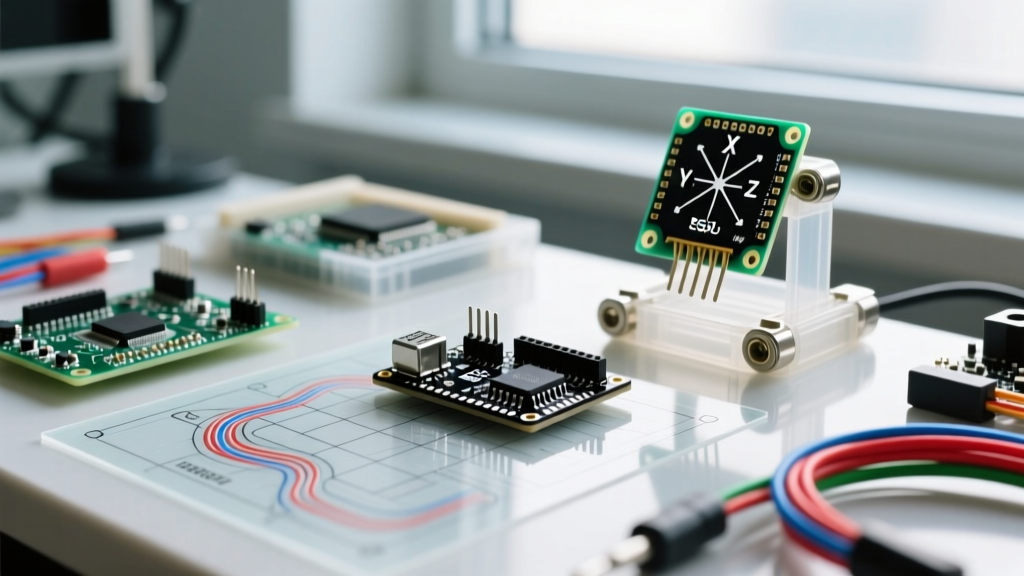
When engineers refer to "nona-axis" data, they are talking about sensor fusion derived from three distinct 3-axis sensors housed in a single package or tightly coupled on a PCB. A true 9-axis IMU provides:
- 3-Axis Accelerometer: Measures linear acceleration (gravity and movement) in X, Y, and Z planes.
- 3-Axis Gyroscope: Measures angular velocity (rate of rotation) around the X, Y, and Z axes.
- 3-Axis Magnetometer: Measures the ambient magnetic field to provide an absolute heading reference (compass).
The Arduino Nano 33 BLE Sense Rev2 is the premier board for this. Unlike the Rev1 which used the STMicroelectronics LSM9DS1, the Rev2 utilizes a highly advanced Bosch BHI260AP smart sensor hub paired with a BMM150 magnetometer. This combination allows for onboard AI processing and hardware-level sensor fusion, drastically reducing the computational load on the nRF52840 MCU.
Hardware Deep Dive: External 9-Axis Alternatives
If you are using a standard 5V Arduino Nano Every, you lack an onboard IMU. To achieve "nona-axis" tracking, you must wire an external 9-DOF breakout board. The industry standard for hobbyists and prototyping engineers remains the Bosch BNO055. As detailed in the Adafruit BNO055 Absolute Orientation Sensor guide, this chip features an internal ARM Cortex-M0 that handles complex sensor fusion algorithms natively, outputting clean quaternion data via I2C.
Wiring a 9-Axis Sensor to a 5V Arduino Nano Every
Integrating a 3.3V 9-axis IMU (like the BNO055 or LSM9DS1) with a 5V Nano Every requires strict attention to logic levels. Do not connect 5V I2C lines directly to a 3.3V sensor. Over time, the overvoltage will degrade the sensor's internal ESD protection diodes, leading to I2C bus lockups and permanent hardware failure.
Engineering Warning: The I2C specification requires pull-up resistors on the SDA and SCL lines. When mixing 5V and 3.3V devices, you must use a bidirectional logic level shifter (such as a BSS138 MOSFET-based breakout) and place 4.7kΩ pull-up resistors on both the low-voltage (3.3V) and high-voltage (5V) sides of the shifter.
Standard I2C Wiring Matrix
- VIN / VCC: Connect to the 3.3V pin on the Nano (or the LV side of your level shifter).
- GND: Common ground between the Nano, the level shifter, and the IMU.
- SDA: Nano Pin A4 (through the level shifter).
- SCL: Nano Pin A5 (through the level shifter).
- INT (Interrupt): Optional, but recommended for reading data without polling. Connect to Nano Pin D2 (supports hardware interrupts).
Sensor Fusion: Why Raw "Nona" Data Isn't Enough
A common mistake among beginners is reading raw accelerometer and gyroscope data and attempting to calculate Euler angles (Pitch, Roll, Yaw) using basic trigonometry. This approach fails in real-world applications due to two phenomena:
- Gyroscopic Drift: Integrating angular velocity over time accumulates mathematical errors, causing your calculated angle to drift endlessly.
- Accelerometer Noise: While accelerometers provide a stable long-term reference to gravity, they are highly susceptible to high-frequency vibration noise from motors and mechanical movement.
To solve this, you must use a Sensor Fusion Algorithm. The Madgwick or Mahony filters are standard in the MCU space. These algorithms use a complementary filter approach (often via quaternions to avoid Gimbal Lock) to blend the short-term accuracy of the gyroscope with the long-term stability of the accelerometer and magnetometer. If you are using the Nano 33 BLE Sense Rev2, the onboard BHI260AP handles this mathematically in hardware, outputting ready-to-use orientation vectors.
Troubleshooting Edge Cases and I2C Failures
When your 9-axis IMU fails to initialize on the I2C bus, the issue is rarely the microcontroller code. It is almost always a physical layer violation. Run through this diagnostic checklist:
- I2C Address Conflicts: The BNO055 defaults to
0x28but can be toggled to0x29by pulling the ADR pin high. The LSM9DS1 uses multiple addresses (0x6Bfor Accel/Gyro,0x1Efor Mag). Use an I2C scanner sketch to verify what the bus actually sees. - Bus Capacitance Limit: The I2C specification limits total bus capacitance to 400pF. If you are using long wires (over 30cm) or multiple sensors on the same bus, the signal edges will degrade, causing NACK (Not Acknowledged) errors. Keep I2C traces under 15cm for 400kHz Fast Mode.
- Magnetic Interference: The "nona-axis" magnetometer is highly sensitive to ferrous metals and current-carrying traces. If your Yaw axis is drifting or offset, ensure the IMU is mounted at least 2 inches away from DC motors, relays, and large copper ground planes.
- Power Brownouts: IMUs require clean power. A sudden spike in MCU radio transmission (e.g., the nRF52840 transmitting BLE data) can cause a voltage droop that resets the IMU. Always place a 100nF ceramic decoupling capacitor as close to the sensor's VCC pin as physically possible.
Final Verdict
While the "Arduino Nona" does not exist as a standalone product, the concept of nona-axis (9-DOF) tracking is a cornerstone of modern robotics, drone stabilization, and VR motion capture. By understanding the reality of the Arduino Nano ecosystem and the strict electrical requirements of 9-axis IMUs, you can bypass the myths and build robust, drift-free spatial tracking systems.