
Introduction to Arduino-Based Parkinsons Monitoring
Designing assistive technology for neurodegenerative conditions requires a precise intersection of hardware calibration, signal processing, and machine learning. When building an Arduino Parkinsons monitoring device, the primary clinical target is the continuous tracking of resting tremors (typically 4–6 Hz) and bradykinesia (slowness of movement). According to clinical data outlined by the National Library of Medicine, these motor fluctuations vary significantly throughout the day based on medication cycles (levodopa half-life), making continuous, wearable telemetry vastly superior to episodic clinical assessments.
This configuration guide details the exact hardware selection, IMU register tuning, TinyML digital signal processing (DSP), and Bluetooth Low Energy (BLE) GATT setup required to build a medical-grade data logger using the Arduino ecosystem in 2026.
Hardware Selection Matrix: Choosing the Right MCU
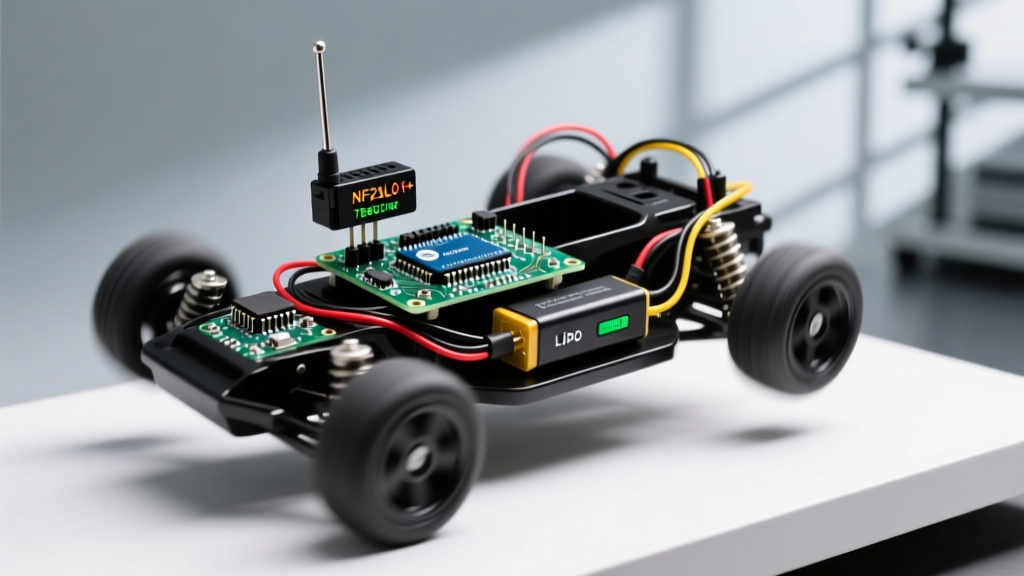
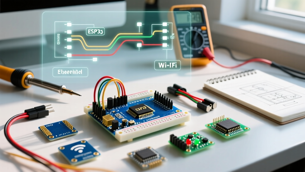
Legacy approaches involved wiring an Arduino Uno to an external MPU6050 breakout board and an SD card shield. While functional for bench tests, this is entirely unsuitable for wearable kinematics due to wiring parasitics, form factor, and power consumption. Modern implementations rely on System-in-Package (SiP) nRF52840 boards with integrated 9-axis IMUs.
| Microcontroller Board | Integrated IMU | Approx. Cost (2026) | Battery / Power Management | Verdict for PD Wearables |
|---|---|---|---|---|
| Arduino Nano 33 BLE Sense Rev2 | BMI270 + BMM150 | $42.00 | Requires external LiPo + charger shield | Best ecosystem support, ideal for Edge Impulse integration. |
| Seeed Studio XIAO nRF52840 Sense | LSM6DS3 | $21.99 | Built-in LiPo charging IC | Best for ultra-compact, lightweight finger/hand mounts. |
| Adafruit Feather nRF52840 Sense | LSM6DS33 + LIS3MDL | $39.95 | Built-in LiPo charging & JST connector | Excellent for rapid prototyping with onboard Qwiic/STEMMA. |
For this guide, we will configure the Arduino Nano 33 BLE Sense Rev2. As noted in the official Arduino hardware documentation, the Rev2 iteration replaces the older LSM9DS1 with the Bosch BMI270, which offers significantly lower noise density and advanced hardware-level FIFO buffering—critical for preventing data loss during BLE transmission bottlenecks.
Step 1: IMU Sensor Calibration and Register Configuration
The most common failure mode in DIY tremor trackers is incorrect accelerometer scaling. Parkinsonian resting tremors exhibit low-amplitude, high-frequency oscillations. If you configure the accelerometer to a ±16g range (often the default in generic libraries), the quantization step size is roughly 0.48 mg/LSB. However, setting it to ±2g yields a resolution of 0.061 mg/LSB, allowing the MCU to resolve micro-tremors that a 16g scale would round down to digital noise.
Arduino C++ Configuration Snippet
Using the Arduino_BMI270_BMM150 library, you must manually override the default Output Data Rate (ODR) and Full Scale (FS) settings in your setup() loop:
#include <Arduino_BMI270_BMM150.h>

void setup() {
  Serial.begin(115200);
  if (!IMU.begin()) {
    Serial.println("Failed to initialize IMU!");
    while (1);
  }
  // Set Accelerometer to 2G for maximum resolution of low-amplitude tremors
  IMU.setAccelFS(2);
  // Set ODR to 119Hz. Nyquist theorem requires >12Hz for 6Hz tremors,
  // but 119Hz provides overhead for motion artifact filtering.
  IMU.setAccelODR(5);

  // Set Gyroscope to 245 dps (degrees per second) for precise rotational tracking
  IMU.setGyroFS(1);
  IMU.setGyroODR(5);
}
Step 2: Edge Impulse TinyML DSP Configuration
Raw time-series data is rarely sufficient for classifying tremor severity against voluntary movement (e.g., reaching for a glass of water). We utilize Edge Impulse to train a neural network to distinguish between Resting Tremor, Postural Tremor, and Voluntary Kinematics. According to the Edge Impulse continuous motion recognition guidelines, configuring the DSP block correctly is paramount.
DSP Block Parameters
- Window Size: 1000 ms. (A 1-second window captures at least four full cycles of a 4 Hz resting tremor, providing a complete spectral picture).
- Window Increase (Stride): 200 ms. (Provides 80% overlap, ensuring we don't miss transient tremor bursts during medication 'off' periods).
- Frequency Domain: Select Spectral Analysis (FFT). Do not use Mel-Frequency Energy (MFE), as MFE is optimized for audio/acoustics, whereas FFT isolates the exact 4–6 Hz kinematic frequency bins.
Feature Extraction Insights
When generating features, pay close attention to the Spectral Power in the 3–8 Hz band. In your training data, ensure you include 'confusion' classes: walking (which introduces a 1.5–2.5 Hz pendulum swing artifact) and typing (which introduces 8–12 Hz sporadic spikes). A well-configured model will achieve an F1 score >0.92 on the validation set by learning to ignore the low-frequency gait artifacts.
Step 3: BLE GATT Telemetry and Connection Intervals
Streaming 119 Hz IMU data continuously over Bluetooth Low Energy will quickly overwhelm standard BLE buffers if the connection interval is left at default settings. The default Arduino BLE library often negotiates a connection interval of 30–50 ms, which can lead to FIFO overruns on the BMI270 sensor.
Optimizing the GATT Service
You must define a custom GATT service and force a tighter connection interval. Use the BLE.setConnectionInterval() function to request a 7.5 ms to 15 ms interval from the central device (e.g., a Raspberry Pi hub or a smartphone app).
BLE.setConnectionInterval(0x0006, 0x000C); // 7.5ms to 15ms
Furthermore, do not send individual float variables. Pack the X, Y, and Z accelerometer and gyroscope readings into a structured byte array (24 bytes per frame) and utilize the Notify characteristic rather than Read. Notify pushes data to the central device the millisecond it is ready, eliminating polling latency.
Physical Mounting and Motion Artifact Rejection
The physical location of the Arduino wearable dictates the signal-to-noise ratio (SNR).
Clinical Maker Note: Do not mount the sensor on the volar wrist (where smartwatches sit). The wrist joint introduces massive noise from flexor/extensor tendon movement and arm swinging.
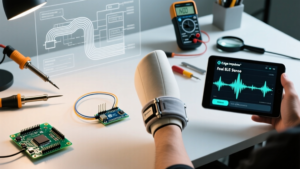
For optimal Parkinsons tremor tracking, configure a custom 3D-printed housing that mounts the Nano 33 BLE Sense to the dorsal metacarpal region (the back of the hand, just below the knuckles). This location is rigidly coupled to the hand's pronation/supination tremors while mechanically filtering out elbow and shoulder kinematics. Use a high-durometer silicone strap (Shore A 60) to prevent sensor micro-movements against the skin, which the accelerometer will falsely interpret as high-frequency tremor noise.
Real-World Failure Modes and Troubleshooting
| Failure Mode | Symptom in Data | Configuration Fix |
|---|---|---|
| Aliasing | Ghost frequencies appearing at 15-20 Hz. | Ensure the BMI270 hardware low-pass filter is enabled. Set filter bandwidth to ODR/4 (approx 30Hz) in the sensor registers. |
| Thermal Drift | Gyroscope Z-axis slowly offsets over 30 minutes. | Implement a 5-second stationary calibration routine at boot to calculate and subtract the zero-rate offset vector. |
| BLE Packet Drops | Timestamps on the Python receiver show missing 50ms chunks. | Reduce BLE MTU size or implement a circular buffer in C++ that batches 6 frames before triggering the GATT Notify event. |
Conclusion and Next Steps
Configuring an Arduino Parkinsons tracking wearable requires moving beyond basic 'read-and-print' tutorials. By strictly defining the ±2g accelerometer range, leveraging FFT-based DSP blocks in Edge Impulse, and tuning the BLE GATT connection intervals to 7.5 ms, makers and researchers can deploy devices that yield clinically actionable telemetry. As you iterate on your hardware housing, consider integrating a MAX30102 pulse oximeter to correlate tremor severity with heart rate variability (HRV), opening new avenues for autonomic nervous system research in PD patients.