
Introduction to NTC Thermistors in MCU Design
While digital sensors like the DS18B20 dominate hobbyist projects, the thermistor Arduino combination remains a staple for high-speed, low-cost analog temperature sensing. NTC (Negative Temperature Coefficient) thermistors offer rapid thermal response times and high sensitivity, making them ideal for 3D printer hotends, battery management systems, and environmental monitoring. However, because their resistance-to-temperature curve is highly non-linear, simply reading an analog voltage is not enough. To extract accurate Celsius readings, we must implement the Steinhart-Hart equation and carefully manage analog-to-digital converter (ADC) noise and thermal self-heating.
In this 2026 guide, we will interface a standard 10K 3950 NTC thermistor with the modern Arduino Uno R4 Minima, leveraging its 14-bit ADC capabilities while maintaining backward compatibility with legacy 10-bit boards.
Bill of Materials (BOM) and 2026 Pricing
Building a precision thermistor circuit requires attention to component tolerances. A standard 5% carbon film resistor will introduce significant temperature drift. Here is the exact hardware profile used for this tutorial:
- Microcontroller: Arduino Uno R4 Minima ($27.50) or Uno R3 ($24.00)
- Sensor: 10K NTC Thermistor, B-constant 3950 (Glass bead or epoxy coated) ($0.50 - $1.20)
- Reference Resistor: 10K Ohm, 1% Tolerance Metal Film Resistor ($0.10)
- Wiring: 22 AWG solid core jumper wires and a standard solderless breadboard
Expert Tip: Always purchase the glass-encapsulated 10K 3950 thermistors rather than the black epoxy-coated ones. Glass beads survive reflow soldering temperatures and offer superior long-term stability, resisting moisture ingress that causes resistance drift in epoxy variants.
The Voltage Divider Circuit Topology
Microcontrollers cannot measure resistance directly; they measure voltage. To convert the thermistor's variable resistance into a readable voltage, we use a voltage divider circuit. By placing a known, fixed resistor in series with the NTC thermistor, the voltage at the junction changes proportionally as the thermistor's resistance shifts with temperature.
Wiring the NTC Thermistor Arduino Circuit
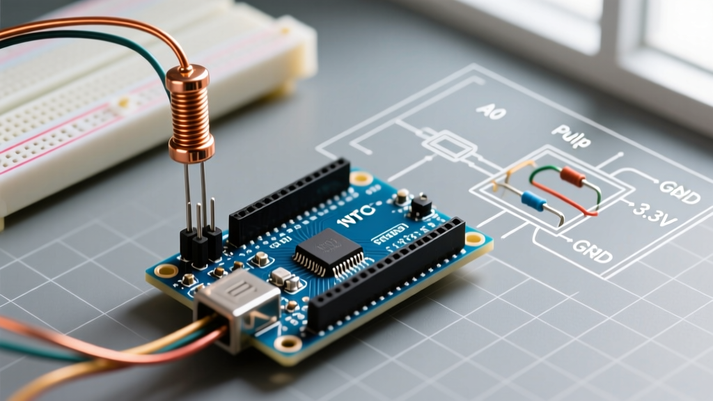
We will use a pull-down configuration (NTC connected to ground). This is generally preferred for NTC sensors because as temperature rises, resistance drops, and the output voltage increases, creating a positive correlation that is easier to debug.
- Connect the 5V pin on the Arduino to one end of the 10K 1% precision resistor.
- Connect the other end of the 10K resistor to the A0 analog input pin on the Arduino.
- Connect one lead of the NTC Thermistor to the A0 pin (the junction point).
- Connect the other lead of the NTC Thermistor to the Arduino GND pin.
The Steinhart-Hart Equation Explained
The relationship between temperature and resistance in an NTC thermistor is exponential. The Omega Engineering thermistor guide details how the Steinhart-Hart equation provides the most accurate mathematical model for this curve over a wide temperature range:
1 / T = A + B * ln(R) + C * (ln(R))^3
- T = Temperature in Kelvin
- R = Resistance of the thermistor in Ohms
- A, B, C = Steinhart-Hart coefficients specific to your thermistor model
For the ubiquitous 10K 3950 NTC thermistor, the manufacturer provides these coefficients. If you are using a different B-constant (like 3380 or 4250), you must calculate A, B, and C using a three-point temperature calibration table, a process thoroughly documented in the Adafruit thermistor tutorial.
For our 10K 3950 sensor, the coefficients are:
- A = 0.001129148
- B = 0.000234125
- C = 0.0000000876741
Precision C++ Implementation
The following code calculates the thermistor resistance based on the ADC reading, applies the Steinhart-Hart equation, and utilizes a 16-sample oversampling technique to smooth out high-frequency electrical noise. This aligns with best practices outlined in the official Arduino analogRead() documentation.
// Thermistor Arduino Steinhart-Hart Implementation
const int THERMISTOR_PIN = A0;
const float SERIES_RESISTOR = 10000.0; // 10K Precision Resistor
const int NUM_SAMPLES = 16; // Oversampling for noise reduction

// Steinhart-Hart Coefficients for 10K 3950 NTC
const float A = 0.001129148;
const float B = 0.000234125;
const float C = 0.0000000876741;

void setup() {
  Serial.begin(115200);
  // Set ADC resolution to 12-bit for Uno R4, ESP32, or RP2040
  // If using a legacy Uno R3, comment out the next line (defaults to 10-bit)
  analogReadResolution(12);
}

void loop() {
  float rawADC = 0;
  // 1. Oversample to reduce ADC noise
  for (int i = 0; i < NUM_SAMPLES; i++) {
    rawADC += analogRead(THERMISTOR_PIN);
    delay(2); // Allow ADC capacitor to settle
  }
  rawADC /= NUM_SAMPLES;

  // Determine max ADC value based on resolution
  float maxADC = pow(2, analogReadResolution()) - 1;

  // 2. Calculate Thermistor Resistance (Pull-down configuration)
  float resistance = SERIES_RESISTOR * (rawADC / (maxADC - rawADC));

  // 3. Apply Steinhart-Hart Equation
  float logR = log(resistance);
  float tempKelvin = 1.0 / (A + B * logR + C * pow(logR, 3));

  // 4. Convert Kelvin to Celsius
  float tempCelsius = tempKelvin - 273.15;

  Serial.print("Resistance: ");
  Serial.print(resistance);
  Serial.print(" Ohms | Temperature: ");
  Serial.print(tempCelsius);
  Serial.println(" °C");

  delay(500);
}
Advanced Troubleshooting: Mitigating Self-Heating and ADC Noise
Even with perfect code, physics can ruin your readings. The most common failure mode in thermistor Arduino projects is thermal self-heating.
The Physics of Self-Heating
When current flows through the thermistor, it dissipates power as heat ($P = I^2R$). A standard glass bead thermistor has a dissipation constant ($\delta$) of roughly $1.5 mW/^\circ C$ in still air. If your circuit pushes too much current, the sensor heats itself, reporting a temperature higher than the ambient environment.
Let us calculate the error for a 5V system with a 10K divider at 25°C (where $R_{ntc} = 10K$):
- Total Resistance = $20,000 \Omega$
- Current ($I$) = $5V / 20,000 \Omega = 0.25 mA$
- Power ($P$) = $(0.00025)^2 \times 10,000 = 0.625 mW$
- Temperature Error ($\Delta T$) = $0.625 mW / 1.5 mW/^\circ C = 0.41 ^\circ C$
A nearly half-degree error is unacceptable for precision work. The Solution: Do not wire the voltage divider directly to the 5V rail. Instead, connect the top of the 10K resistor to a digital I/O pin. Set the pin to OUTPUT and HIGH only 10 milliseconds before taking the reading, then set it to LOW immediately after. This reduces the duty cycle, effectively eliminating self-heating.
Sensor Comparison Matrix
Is an NTC thermistor the right choice for your specific 2026 project? Compare it against other common MCU temperature sensors below.
| Sensor Type | Example Model | Accuracy | Interface | Cost (2026) | Best Use Case |
|---|---|---|---|---|---|
| NTC Thermistor | 10K 3950 Glass | ±0.2°C (Calibrated) | Analog (ADC) | $0.50 | High-speed thermal runaway detection, 3D printer hotends |
| Digital IC | DS18B20 | ±0.5°C | 1-Wire Digital | $2.50 | Long-distance wiring, waterproof liquid sensing |
| Analog IC | TMP36 | ±1.0°C | Analog (Voltage) | $1.80 | Basic ambient room monitoring (linear output) |
| RTD | PT1000 | ±0.1°C | Resistance (Requires Amp) | $8.00+ | Industrial HVAC, laboratory-grade precision |
By understanding the underlying math, respecting component tolerances, and engineering around physical limitations like self-heating, you can transform a $0.50 analog component into a laboratory-grade temperature sensor for your next microcontroller build.